S7-200 Specifications
A-69
S7-200 Programmable Controller System Manual
A5E00066097-02
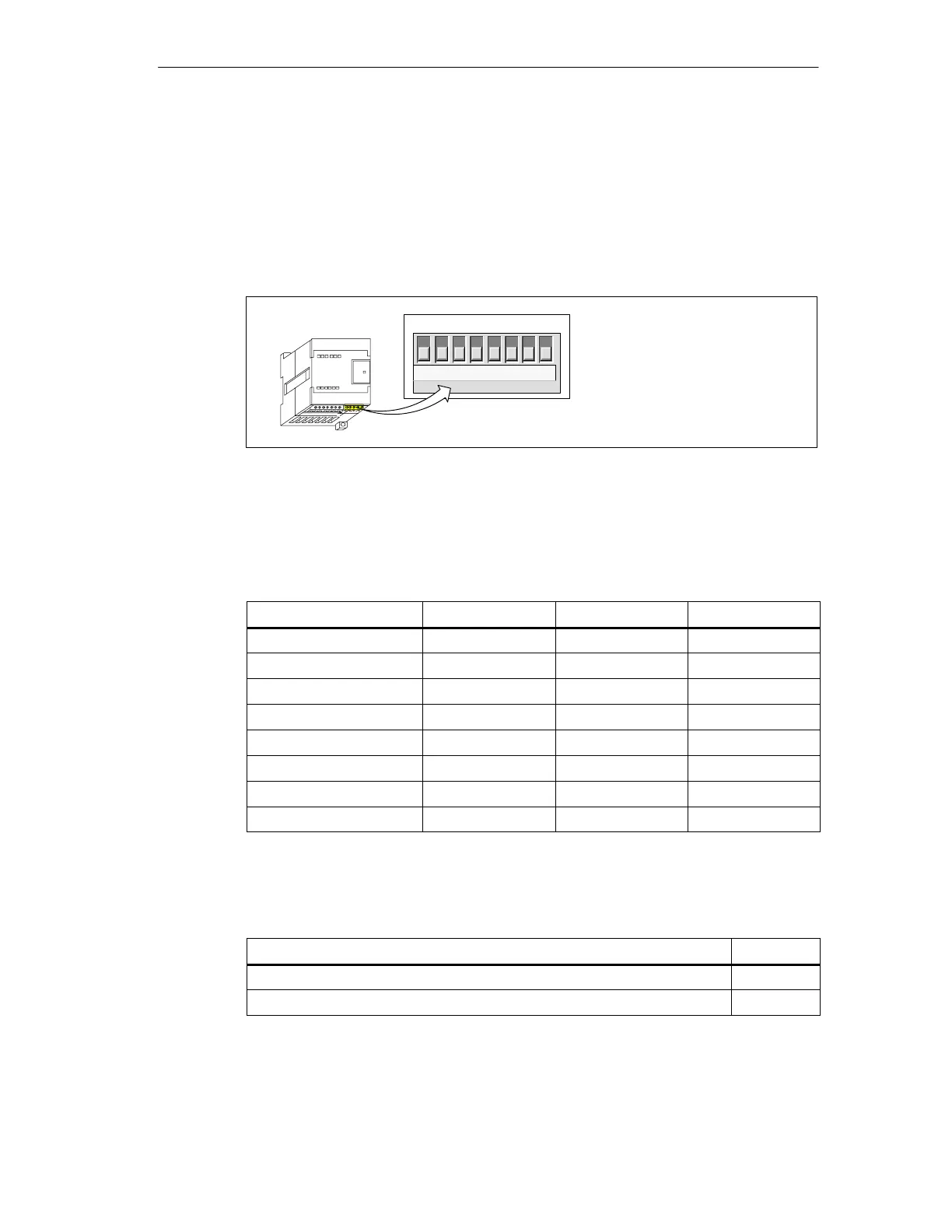
Configuring the EM 231 Thermocouple Module
The configuration DIP switches are located on the bottom of the module, as shown
in Figure A-35. For the DIP switch settings to take effect, you need to power cycle
the PLC and/or the user 24V
power supply.
DIP switch 4 is reserved for future use. Set DIP switch 4 to the 0 (down) position.
Refer to Table A-22 through Table A-26 for other DIP switch settings.
↑1 - On
↓0 - Off
1234*56
DIP ON ↑
Configuration
78
* Set dipswitch 4 to the 0 (down) position.
Figure A-35 Configuring DIP Switches for the EM 231 Thermocouple Module
Selecting the thermocouple type Select the thermocouple type by setting DIP
switches 1, 2, and 3 as shown in Table A-42.
Table A-22 Selecting the Thermocouple Type
Thermocouple Type
SW1 SW2 SW3
J (Default) 0 0 0
K 0 0 1
T 0 1 0
E 0 1 1
R 1 0 0
S 1 0 1
N 1 1 0
+/-80mV 1 1 1
Selecting the sensor burnout direction Select the sensor burnout direction
(either upscale or downscale) by setting DIP switch 5 as shown in Table A-23.
Table A-23 Selecting Sensor Burnout Direction
Burnout Direction
SW5
Upscale (+3276.7 degrees) 0
Downscale (-3276.8 degrees) 1

 Loading...


