Setting Up Communications Hardware and Network Communications
7-32
S7-200 Programmable Controller System Manual
A5E00066097-02
7.6 Network Components
The communication port on each S7-200 enables you to connect it to a network
bus. The information below describes this port, the connectors for the network bus,
the network cable, and repeaters used to extend the network.
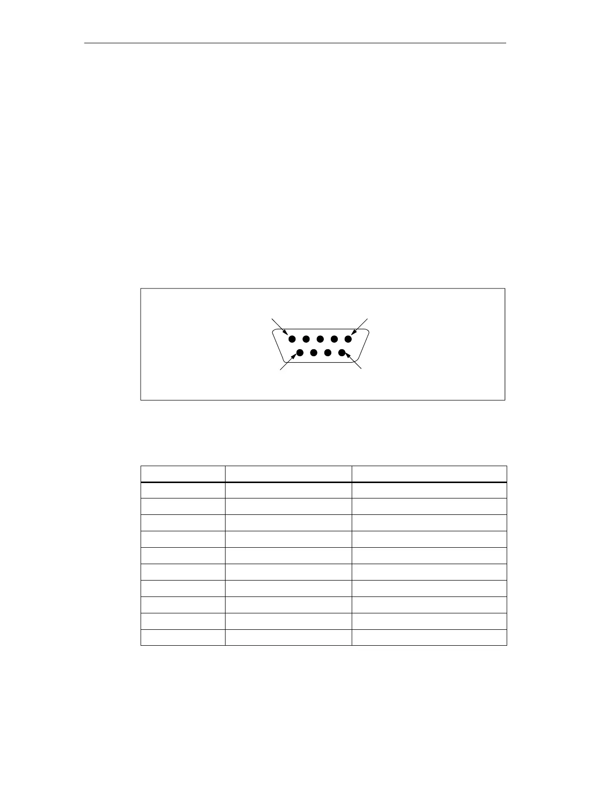
Communication Port
The communication ports on the S7-200 CPUs are RS-485 compatible on a
nine-pin subminiature D connector in accordance with the PROFIBUS standard as
defined in the European Standard EN 50170. Figure 7-23 shows the connector that
provides the physical connection for the communication port, and Table 7-5
describes the communication port pin assignments. See Appendix A for
information about the EM 277 PROFIBUS-DP module.
Pin 6
Pin 1
Pin 9
Pin 5
Figure 7-23 Pin Assignment for the S7-200 CPU Communication Port
Table 7-5 S7-200 Communication Port Pin Assignments
Pin Number PROFIBUS Designation Port 0/Port 1
1 Shield Chassis ground
2 24 V Return Logic common
3 RS-485 Signal B RS-485 Signal B
4 Request-to-Send RTS (TTL)
5 5 V Return Logic common
6 +5 V +5 V, 100 Ω series resistor
7 +24 V +24 V
8 RS-485 Signal A RS-485 Signal A
9 Not applicable 10-bit protocol select (input)
Connector shell Shield Chassis ground

 Loading...


