Conventions for S7-200 Instructions
8-2
S7-200 Programmable Controller System Manual
A5E00066097-02
8.1 Concepts and Conventions For STEP 7-Micro/WIN 32
Programming
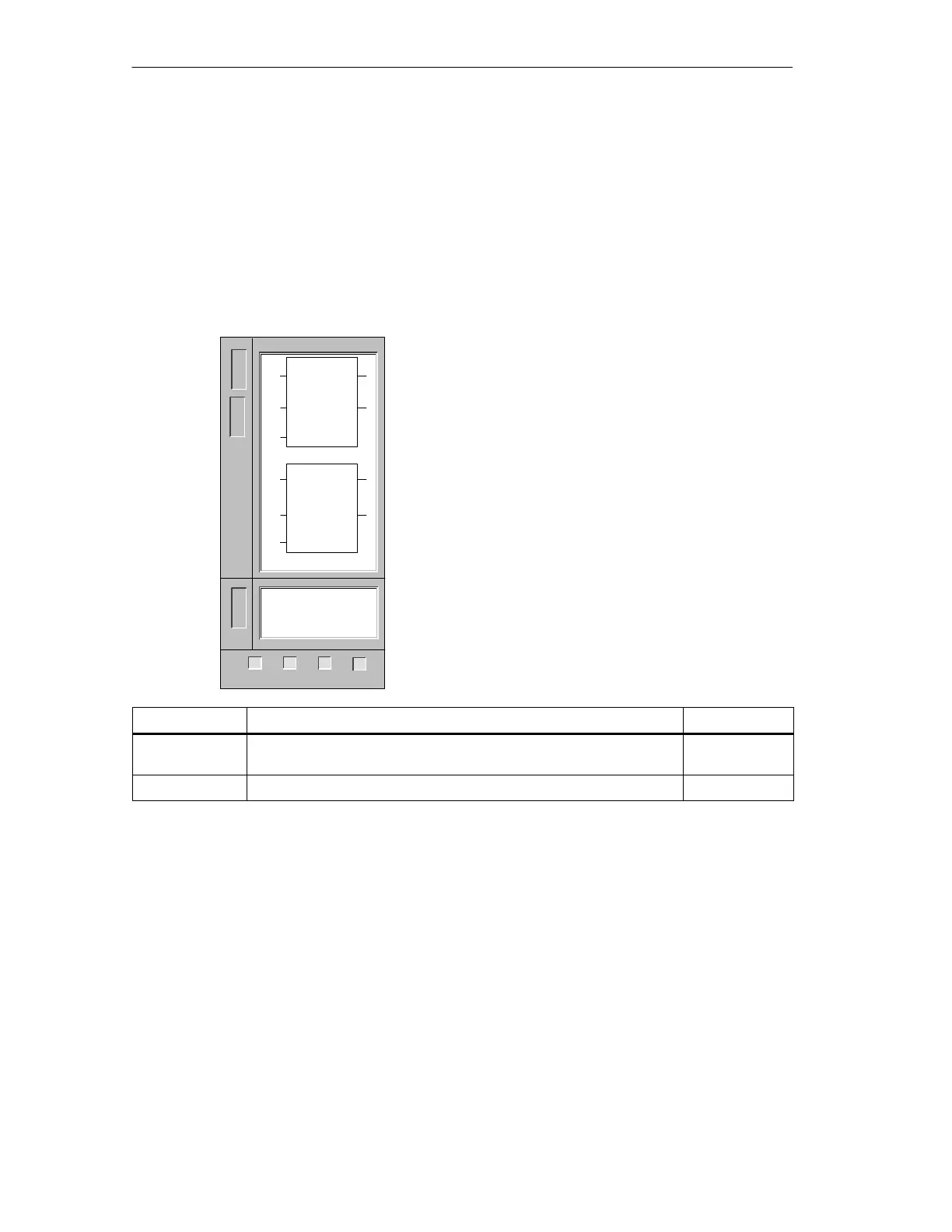
The following diagram shows the STEP 7-Micro/WIN 32 instruction format as used
throughout this chapter. A description of the components of the instruction format
follows the diagram.
Add Integer and Subtract Integer
The Add Integer and Subtract Integer instructions add
or subtract two 16-bit integers and produce a 16-bit result
(OUT).
In LAD and FBD: IN1 + IN2 = OUT
IN1 - IN2 = OUT
In STL: IN1 + OUT = OUT
OUT - IN1 = OUT
Error conditions that set ENO = 0: SM1.1 (overflow),
SM4.3 (run-time), 0006 (indirect address)
These instructions affect the following Special Memory
bits: SM1.0 (zero); SM1.1 (overflow); SM1.2 (negative)
Inputs/Outputs Operands Data Types
IN1, IN2 VW, IW, QW, MW, SW, SMW, LW, AIW, T, C, AC, Constant, *VD,
*AC, *LD
INT
OUT VW, IW, QW, MW, SW, SMW, LW, T, C, AC, *VD, *AC, *LD INT
Title of the Instruction or Instruction Group: In this example Add Integer and
Subtract Integer is the title.
Figure Showing the STEP 7-Micro/WIN 32 Instruction: The figure below the
instruction title contains a picture of the LAD instruction element, the FBD
instruction element and for SIMATIC instructions, the STL instruction mnemonics
and operands. In some cases, the picture of the LAD and FBD instructions are the
same, and only one box containing both the LAD and FBD picture is shown (this is
the case in this example). The SIMATIC STL instruction mnemonics and operands
always appear in a separate box.
In the example, the LAD/FBD pictures have three inputs (inputs are always on the
left side of the picture) and two outputs (outputs are always on the right side of the
picture). In LAD there are two basic types of inputs and outputs. The first type of
input/output is a power flow input or output.
L
A
D
S
T
L
+I IN1, OUT
-I IN1, OUT
OUT
ADD_I
EN
IN1
IN2
OUT
OUT
SUB_I
EN
IN1
IN2
OUT
ENO
ENO
F
B
D
222 224
✓✓✓
221
226
✓

 Loading...


