S7-200 Specifications
A-68
S7-200 Programmable Controller System Manual
A5E00066097-02
24V
ConfigurationConfiguration
24 VDC power and
common terminals
EM 231
AI 2 x RTD
EM 231 RTD
24V
+
-
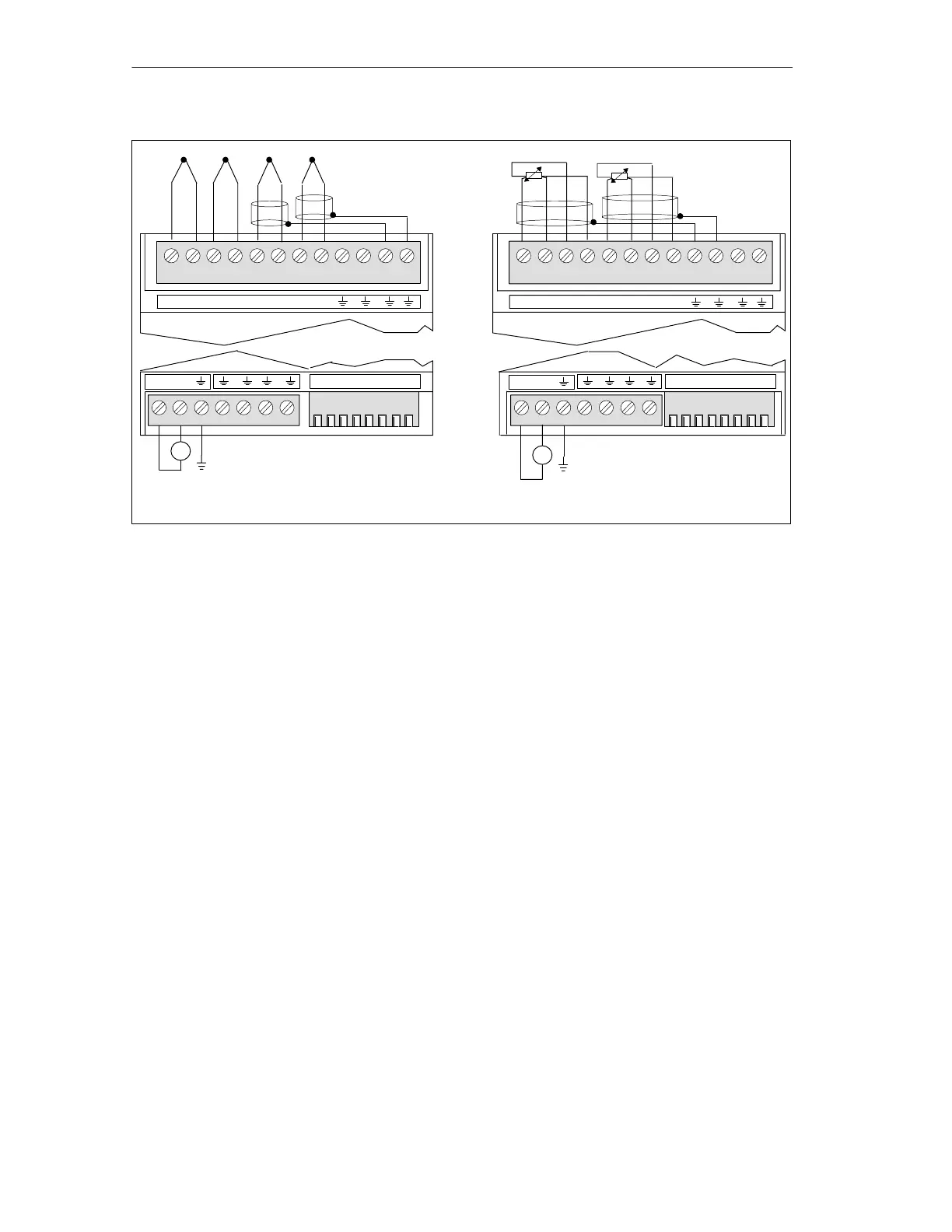
A+ A – B+ B– C+ C– D+
24 VDC power and
common terminals
D–
EM 231
AI 4
EM 231 TC
+
-
+-+-++- -
A+ A – a+ a– B+ B– b+ b–
ML+
ML+
Figure A-34 Connector Terminal Identification for EM 231 Thermocouple and RTD
Compatibility
The RTD and Thermocouple modules are designed to work with the S7-200
CPU 222, CPU 224, and CPU 226.
These modules are designed to give maximum performance when installed in a
stable temperature environment. The EM 231 Thermocouple module, for example,
has special cold junction compensation circuitry that measures the temperature at
the module connectors and makes necessary changes to the measurement to
compensate for temperature differences between the reference temperature and
the temperature at the module. If the ambient temperature is changing rapidly in
the area where the EM 231 Thermocouple module is installed, additional errors are
introduced. To achieve maximum accuracy and repeatability, Siemens
recommends that the S7-200 RTD and thermocouple modules be mounted in
locations that have stable ambient temperature.
EM 231 Thermocouple Module
The EM 231 Thermocouple module provides a convenient, isolated interface for
the S7-200 family to seven thermocouple types: J, K, E, N, S, T, and R. It allows
the S7-200 to connect to low level analog signals, 80mV range. You must use
DIP switches to select the thermocouple type, open wire check, temperature scale,
cold junction compensation and burnout direction. All thermocouples attached to
the module must be of the same type.

 Loading...


