S7-200 Specifications
A-77
S7-200 Programmable Controller System Manual
A5E00066097-02
EM 231 RTD Module
The EM 231 RTD module provides a convenient interface for the S7-200 family to
several different RTDs. It also allows the S7-200 to measure three different
resistance ranges. You must use DIP switches to select RTD type, wiring
configuration, temperature scale, and burnout direction. Both RTDs attached to the
module must be of the same type.
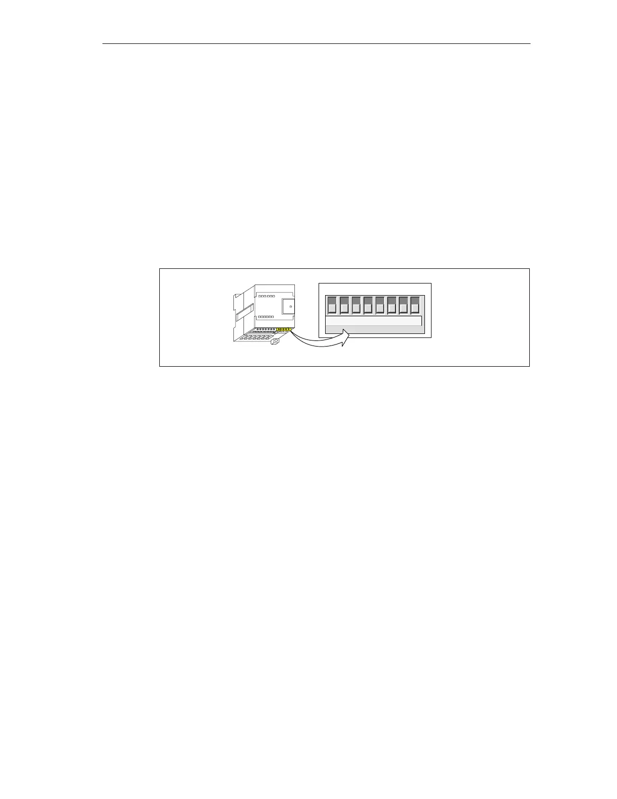
Configuring the EM 231 RTD Module
The configuration DIP switches are located on the bottom of the module, as shown
in Figure A-37. For the DIP switch settings to take effect, you need to power cycle
the PLC and/or the user 24V
power supply.
↑1 - On
↓0 - Off
123456
DIP ON ↑
Configuration
78
Figure A-37 Configuring DIP Switches for the RTD Module
Selecting the RTD type Select RTD type by setting DIP switches 1, 2, 3, 4, and 5
to correspond to the RTD as shown in Table A-30.

 Loading...


