Installing an S7-200 PLC
2-16
S7-200 Programmable Controller System Manual
A5E00066097-02
2.4 Using Suppression Circuits
General Guidelines
Equip inductive loads with suppression circuits that limit voltage rise on loss of
power. Use the following guidelines to design adequate suppression. The
effectiveness of a given design depends on the application, and you must verify it
for a particular use. Be sure all components are rated for use in the application.
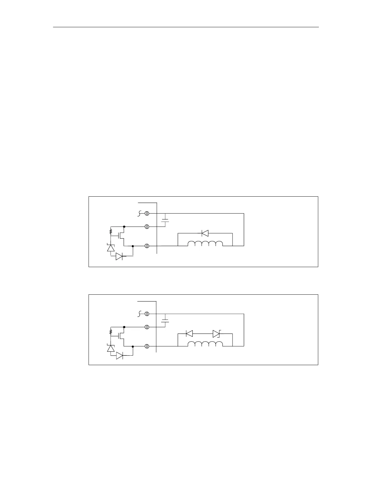
Protecting DC Transistors
The S7-200 DC transistor outputs include zener-controlled clamping that is
adequate for many installations. Use external suppression diodes for either large or
frequently switched inductive loads to prevent overpowering the internal circuits.
Figure 2-13 and Figure 2-14 show typical applications for DC transistor outputs.
+VDC
[a] IN4001 diode or
equivalent
[a]
Inductor
36 V
Figure 2-13 Diode Suppression for DC Transistor Outputs
+VDC
[a] IN4001 diode or
equivalent
[a]
Inductor
[b]
[b] 8.2 V zener, 5W
36 V
Figure 2-14 Zener Diode Suppression for DC Transistor Outputs

 Loading...


