Installing an S7-200 PLC
2-13
S7-200 Programmable Controller System Manual
A5E00066097-02
Guidelines for AC Installation
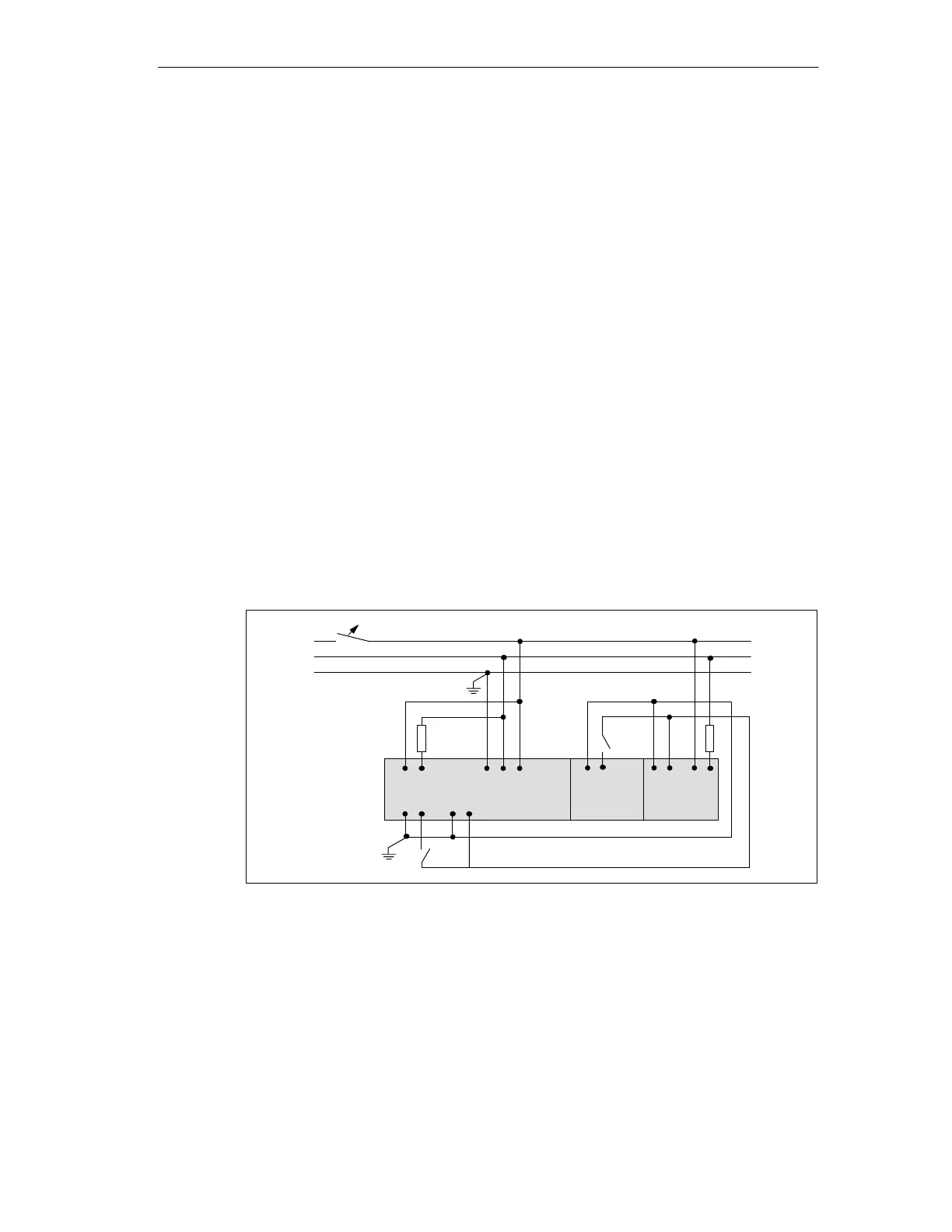
The following items are general wiring guidelines for AC installations. Refer to
Figure 2-11.
[a] Provide a single disconnect switch that removes power from the CPU, all
input circuits, and all output (load) circuits.
[b] Provide overcurrent devices to protect the CPU power supply, the output
points, and the input points. You can also fuse each output point individually
for greater protection.
[c] External overcurrent protection for input points is not required when you
use the 24 VDC sensor supply from the Micro PLC. This sensor supply is
short-circuit protected.
[d] Connect all S7-200 ground terminals to the closest available earth ground
to provide the highest level of noise immunity. It is recommended that all
ground terminals be connected to a single electrical point. Use 14 AWG or 1.5
mm
2
wire for this connection.
[e] DC sensor supply from the CPU may be used for CPU inputs,
[f] expansion DC inputs, and [g] expansion relay coils. This sensor supply is
short-circuit protected.
[h] In most installations, you will have the best noise immunity if you connect
the sensor supply M terminal to ground.
L1
N
PE
[a]
[d]
DO
DI
PST
M L+
[c]
S7-200
AC/DC/Rly
DI
EM 221 DC
DO
EM 222 Rly
[e]
[f] [g]
[b]
[h]
Figure 2-11 120 VAC/230 VAC Using a Single Overcurrent Switch to Protect the CPU and
Load Wiring

 Loading...


