S7-200 Specifications
A-71
S7-200 Programmable Controller System Manual
A5E00066097-02
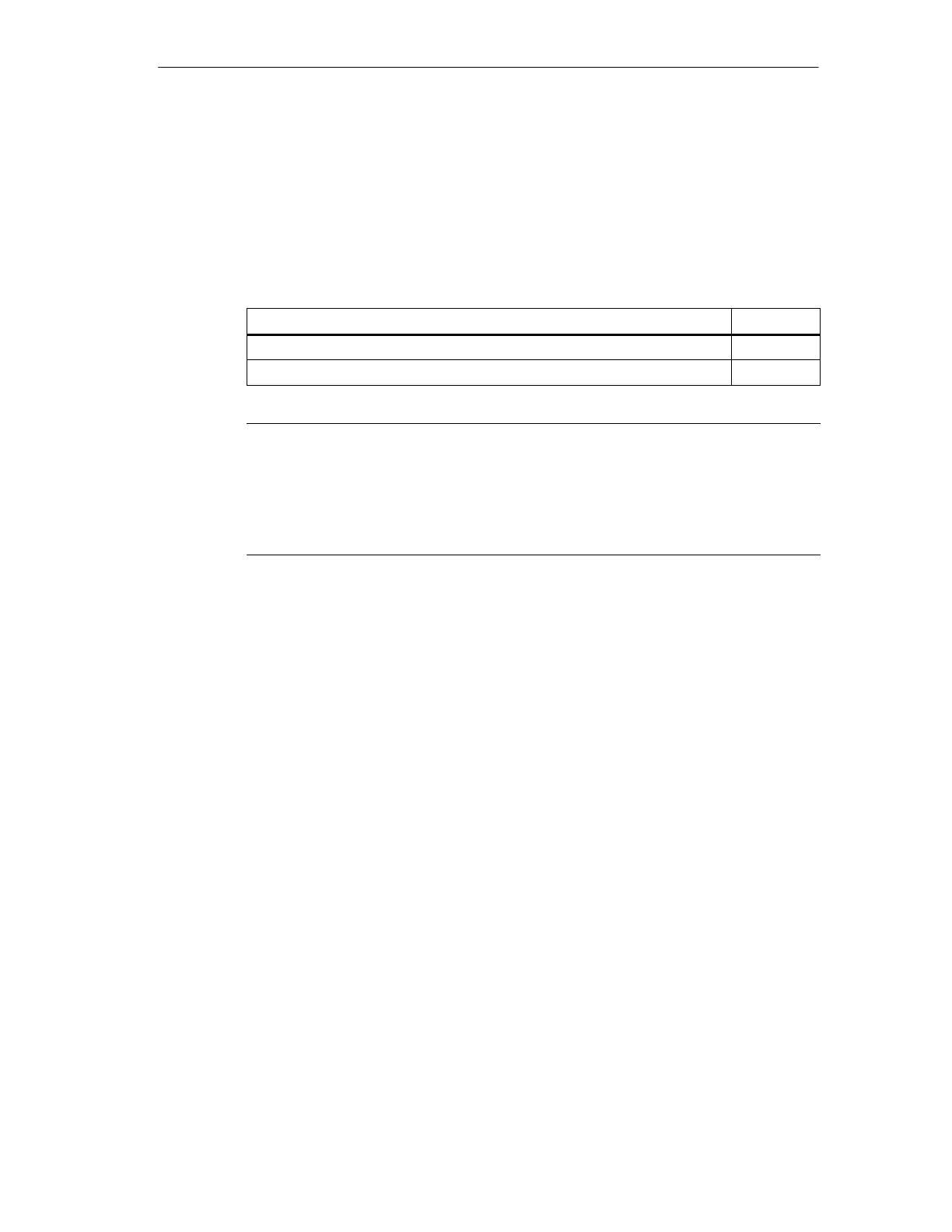
Selecting cold junction operation Cold junction compensation must be enabled
when you are using thermocouples. If cold junction compensation is not enabled,
the conversions from the module will be in error because of the voltage that is
created when the thermocouple wire is connected to the module connector. Cold
junction is automatically disabled when you select the 80mV range. Use DIP
switch 8 to enable or disable cold junction compensation as shown in Table A-26.
Table A-26 Selecting Cold Junction Operation
Cold Junction Enable
SW8
Cold junction compensation enabled 0
Cold junction compensation disabled 1
Note
• Module error may exceed specifications while the ambient temperature is
changing.
• Exceeding the module ambient temperature range specification may cause
the module cold junction to be in error.
Wiring the EM 231 Thermocouple Module
Wire the thermocouple wires directly to the
EM 231 Thermocouple module. Use
shielded wires for best noise immunity. If you are using shielded wires, you should
connect the shield to the grounds on pins 1 to 4 of the signal connector. This
ground is the same ground that is present on the power connector pins 3 to 7. If a
thermocouple input channel is not used, you should short the unused channel
inputs, or connect them in parallel to another channel. This prevents errors
(resulting from floating inputs) from blocking error indications from valid channels.
You must connect user power to pins 1 and 2 of the power connector. You must
connect pin 3 of the power connector to a nearby chassis ground. See
Figure A-36.

 Loading...


