Using USS Protocol Instructions to Communicate with Drives
11-17
S7-200 Programmable Controller System Manual
A5E00066097-02
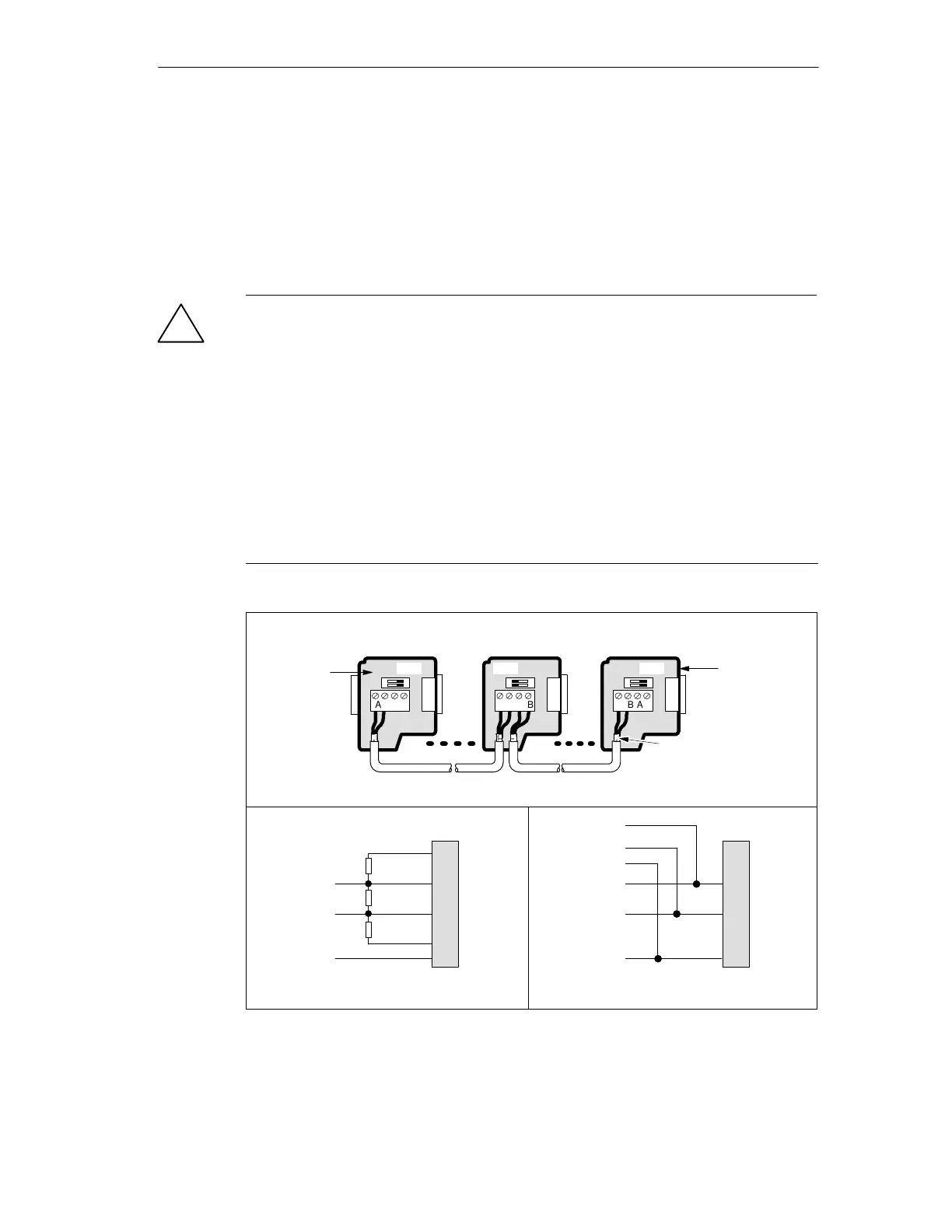
11.4 Connecting the Drives
The standard PROFIBUS cable and connectors can be used to connect the CPU
to the MicroMaster drive. See Network Connectors in Chapter 7 for more
information. See Figure 11-8 for the proper cable bias and termination of the
interconnecting cable.
!
Caution
Interconnecting equipment with different reference potentials can cause unwanted
currents to flow through the interconnecting cable.
These unwanted currents can cause communication errors or can damage
equipment.
Be sure all equipment that you are about to connect with a communication cable
either shares a common circuit reference or is isolated to prevent unwanted
current flows. See “Grounding and Circuit Reference Point for Using Isolated
Circuits” in Section 2.3.
The shield must be tied to chassis ground or terminal 1 on the 9-pin connector. It
is recommended that you tie terminal 2-0V on the MicroMaster drive to chassis
ground.
ABAB
ABAB
On On
ABAB
Off
Switch position = On
Terminated and biased
Switch position = Off
No termination or bias
Switch position = On
Terminated and biased
Cable must be
terminated and biased
at both ends.
Interconnecting cable
390 Ω
220 Ω
390 Ω
B
A
TxD/RxD +
TxD/RxD -
Cable shield
6
3
8
5
1
Network
connector
Pin #
B
A
TxD/RxD +
TxD/RxD -
Cable shield
Network
connector
A
B
Switch position = Off
No termination or bias
TxD/RxD +
TxD/RxD -
Cable shield
Switch position = On
Terminated and biased
Bare shielding
(~12 mm or 1/2 in.) must
contact the metal guides
of all locations.
6
3
8
5
1
Pin #
Network
connector with
programming
port
Network
connector
Figure 11-8 Bias and Termination of Interconnecting Cable

 Loading...


