S7-200 Specifications
A-46
S7-200 Programmable Controller System Manual
A5E00066097-02
Output Data Word Format for EM 232 and EM 235
Figure A-23 shows where the 12-bit data value is placed within the analog output
word of the CPU.
15
4
MSB LSB
0AQW XX
0
00 0
3
14
Data value 11 Bits
Current output data format
15
3
MSB LSB
AQW XX
0
00 0Data value 12 Bits
Voltage output data format
4
0
0
Figure A-23 Output Data Word Format for EM 232 and EM 235
Note
The 12 bits of the digital-to-analog converter (DAC) readings are left-justified in
the output data word format. The MSB is the sign bit: zero indicates a positive
data word value. The four trailing zeros are truncated before being loaded into
the DAC registers. These bits have no effect on the output signal value.
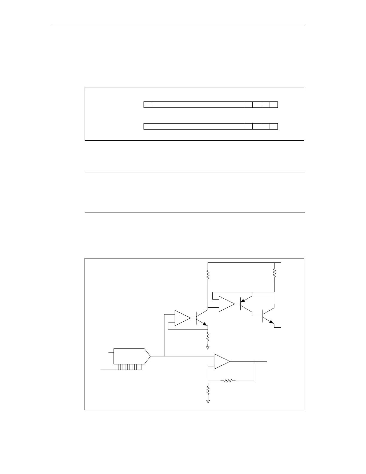
Output Block Diagram for EM 232 and EM 235
Figure A-24 shows the EM 232 and EM 235 output block diagrams.
DATA
11 0
Vref
D/A converter
Digital-to-analog converter
+
-
R
R
Vout
-10.. +10 Volts
M
Voltage output buffer
+/- 2V
+
-
R
M
+
-
R
Iout
0..20 mA
100
+24 Volt
Voltage-to-current converter
1/4
Figure A-24 EM 232 and EM 235 Output Block Diagram

 Loading...


