Setting Up Communications Hardware and Network Communications
7-40
S7-200 Programmable Controller System Manual
A5E00066097-02
Switch 4 of the PC/PPI cable tells the S7-200 CPU to use either a 10-bit protocol
or the normal 11-bit PPI protocol. Switch 4 is used only when the CPU is
communicating with STEP 7-Micro/WIN. If you are not using STEP 7-Micro/Win
with a modem, switch 4 should be left in the 11-bit setting for proper operation with
other devices.
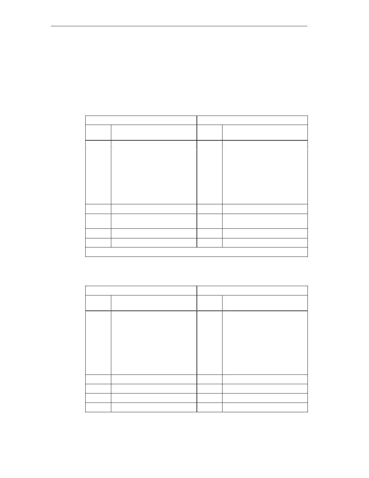
Table 7-10 Pin-outs for RS-485 to RS-232 DTE Connector
RS-485 Connector Pin-out RS-232 DTE Connector Pin-out
1
Pin
Number
Signal Description Pin
Number
Signal Description
1 Ground (RS-485 logic ground) 1 Data Carrier Detect (DCD) (not used)
2 24 V Return (RS-485 logic ground) 2 Receive Data (RD)
(input to PC/PPI cable)
3 Signal B (RxD/TxD+) 3 Transmit Data (TD)
(output from PC/PPI cable)
4 RTS (TTL level) 4 Data Terminal Ready (DTR)
(not used)
5 Ground (RS-485 logic ground) 5 Ground (RS-232 logic ground)
6 +5 V (with 100 Ω series resistor) 6 Data Set Ready (DSR) (not used)
7 24 V Supply 7 Request To Send (RTS)
(output from PC/PPI cable)
8 Signal A (RxD/TxD-) 8 Clear To Send (CTS) (not used)
9 Protocol select 9 Ring Indicator (RI) (not used)
1
A conversion from female to male, and a conversion from 9-pin to 25-pin is required for modems
Table 7-11 Pin-outs for RS-485 to RS-232 DCE Connector
RS-485 Connector Pin-out RS-232 DCE Connector Pin-out
Pin
Number
Signal Description
Pin
Number
Signal Description
1 Ground (RS-485 logic ground) 1 Data Carrier Detect (DCD) (not used)
2 24 V Return (RS-485 logic ground) 2 Receive Data (RD)
(output from PC/PPI cable)
3 Signal B (RxD/TxD+) 3 Transmit Data (TD)
(input to PC/PPI cable)
4 RTS (TTL level) 4 Data Terminal Ready (DTR)
(not used)
5 Ground (RS-485 logic ground) 5 Ground (RS-232 logic ground)
6 +5 V (with 100 Ω series resistor) 6 Data Set Ready (DSR) (not used)
7 24 V Supply 7 Request To Send (RTS) (not used)
8 Signal A (RxD/TxD-) 8 Clear To Send (CTS) (not used)
9 Protocol select 9 Ring Indicator (RI) (not used)

 Loading...


