Setting Up Communications Hardware and Network Communications
7-39
S7-200 Programmable Controller System Manual
A5E00066097-02
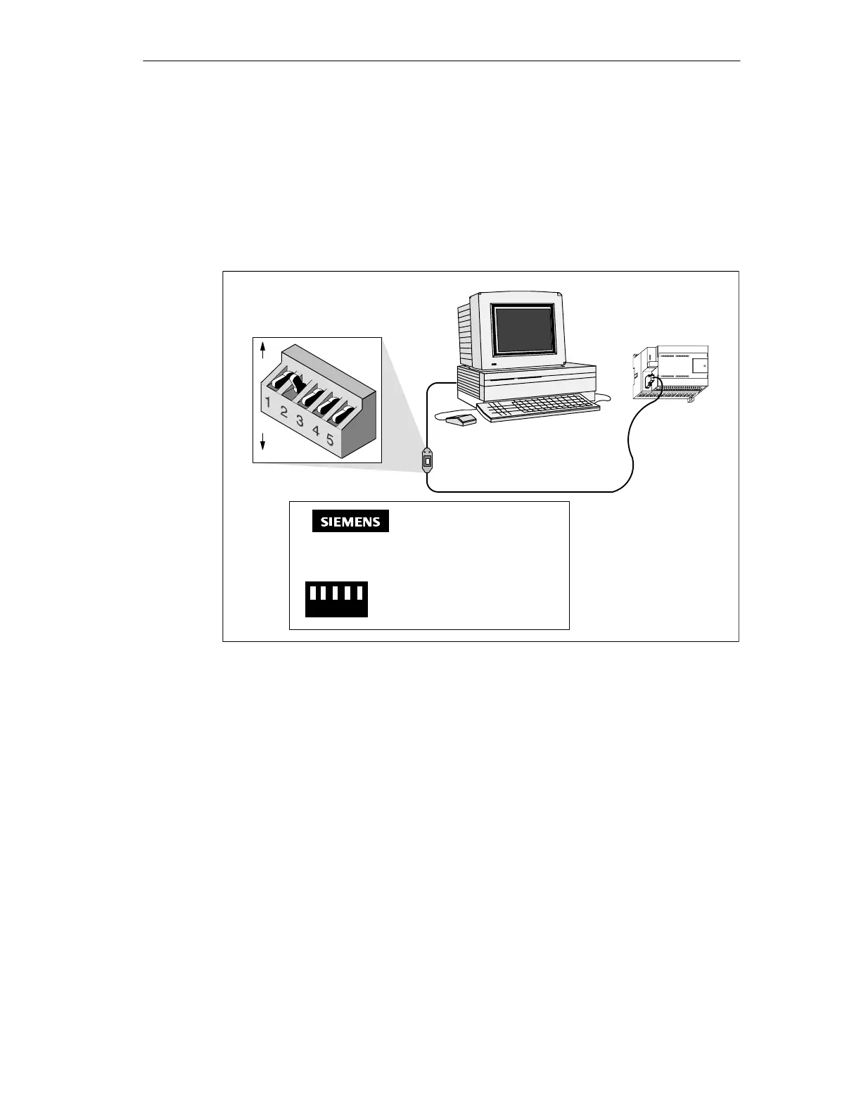
To set the mode to Data Communications Equipment (DCE), you should set
switch 5 to the 0 or down position (see Figure 7-27). To set the mode to Data
Terminal Equipment (DTE), you should set switch 5 to the 1 or up position.
Table 7-10 shows the pin numbers and functions for the RS-485 to RS-232 port of
the PC/PPI cable in DTE mode. Table 7-11 shows the pin numbers and functions
for the RS-485 to RS-232 port of the PC/PPI cable in DCE mode. You should note
that the PC/PPI cable supplies RTS only when it is in DTE mode.
PC/PPI cable
1
RS-232
0
DIP switch settings (down = 0, up = 1):
RS-485
S7-200 CPU
Computer
Isolated
PC/PPI Cable
123 45
1
0
PPI
Baud
Rate 123 SWITCH 4 1 = 10 BIT
38.4K 000 0 = 11 BIT
19.2K 001
9.6K 010 SWITCH 5 1 = DTE
2.4K 100 0 = DCE
1.2K 101
PC
Figure 7-27 Communicating with a CPU in PPI Mode

 Loading...


