IEC 1131-3 Instructions
10-2
S7-200 Programmable Controller System Manual
A5E00066097-02
10.1 IEC Bit Logic Instructions
Table 10-1 gives page references for the non-standard IEC Bit Logic instructions.
Table 10-1 Non-Standard IEC Bit Logic Instructions
Description
Page
Standard Contacts 9-2
Immediate Contacts 9-3
Not Contact 9-4
Positive and Negative Transition 9-4
Output Contact 9-6
Output Immediate 9-6
Set and Reset (N Bits) 9-7
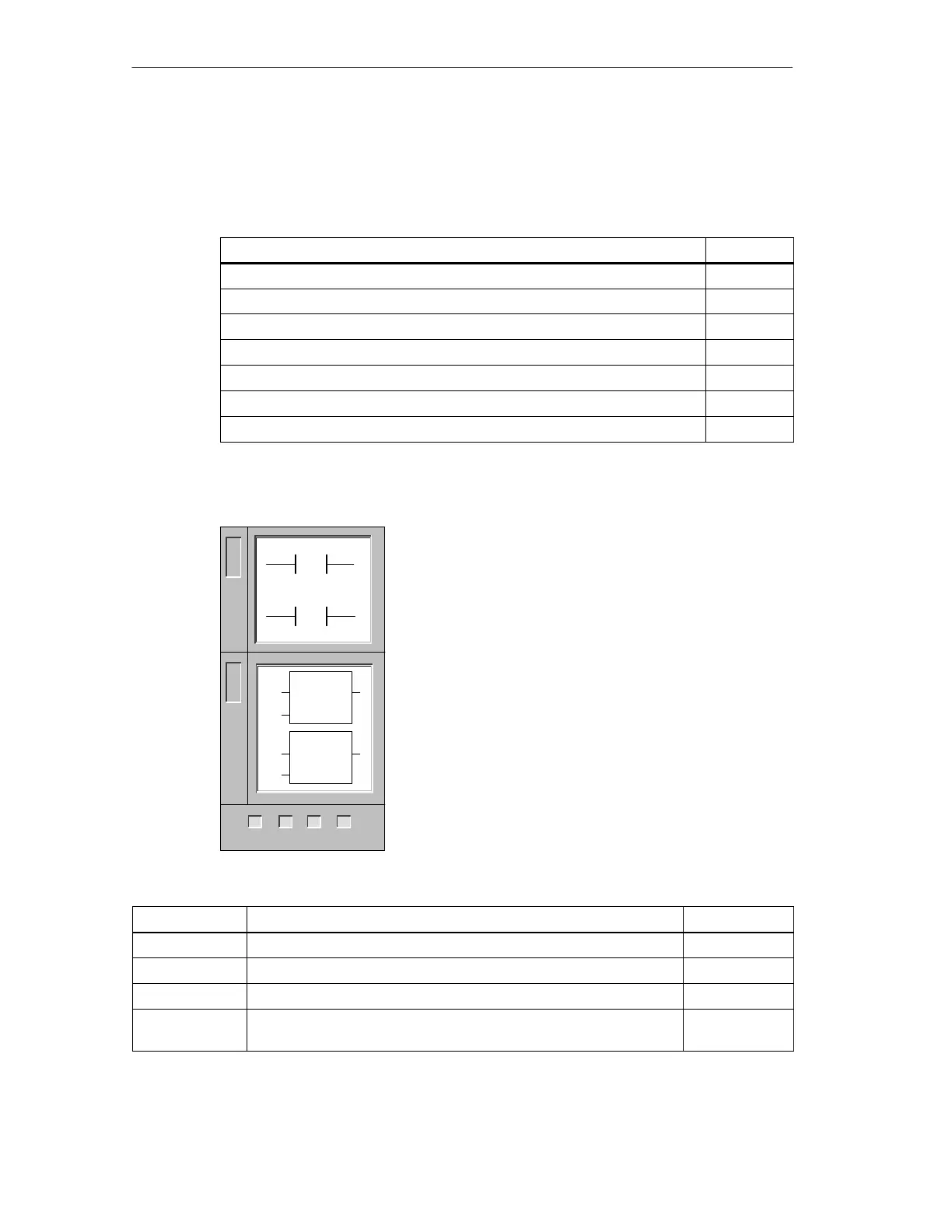
Standard Contacts (non-standard IEC 1131-3)
The Normally Open contact is closed (on) when the bit
is equal to 1.
The Normally Closed contact is closed (on) when the bit
is equal to 0.
These instructions obtain the referenced value from
memory or from the process image register if the
memory type is I or Q.
In LAD, normally open and normally closed instructions
are represented by contacts.
In FBD, normally open instructions are represented by
AND/OR boxes. These instructions can be used to
manipulate Boolean signals in the same manner as
ladder contacts. Normally closed instructions are also
represented by boxes. A normally closed instruction is
constructed by placing the negation symbol on the stem
of the input signal. Inputs to both the AND and OR boxes
can be expanded to a maximum of seven inputs.
Inputs/Outputs Operands Data Types
bit (LAD, STL) I, Q, M, SM, T, C, V, S, L BOOL
Input (LAD) Power Flow BOOL
Inputs (FBD) I, Q, M, SM, T, C, V, S, L, Power Flow BOOL
Output (LAD,
FBD)
I, Q, M, SM, T, C, V, S, L, Power Flow BOOL
L
A
D
bit
bit
/
F
B
D
AND
OR
222 224
✓✓✓
221 226
✓

 Loading...


