S7-200 Specifications
A-38
S7-200 Programmable Controller System Manual
A5E00066097-02
+
+
.7.1.0
1M
.7
1M
+
.0 .1 .2 .31L+
24 VDC Power, Ground and Output Terminals
.42M 2L+ .7 .0 .1
+
.5 .6 3M 3L+ .2 .3 .4 .5 .6 .7
.3.2 .4 .5 .6
5.6 KΩ
470 Ω
2M
.0 .1 .2 .3 .4 .5 .6
24 VDC Commons and 24 VDC Input Terminals
+
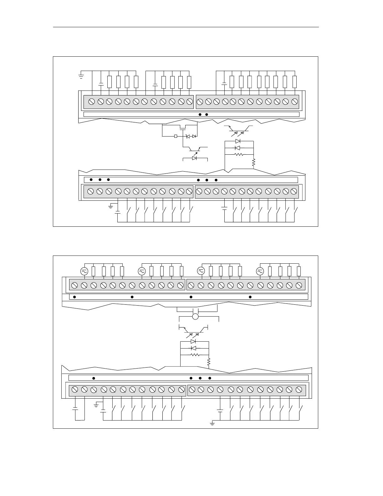
Note:
1. Actual component values may vary.
2. Either polarity accepted
3. DC circuit grounds are optional.
36V
Figure A-17 Connector Terminal Identification for EM 223 16 x 24 VDC In/ 16 x 24 VDC Out
N (-)
L (+)
.0 .1 .2 .33L
M
.0 .1 .2 .31L
4L
Note:
1. Actual component values may vary.
2. Either polarity accepted
3. DC circuit grounds are optional.
4. Relay coil power M must connect to
sensor supply M of CPU.
.4 .5 .6 .7
+
2M
.0 .1 .2 .3
.4 .5 .6 .7
1M
5.6 KΩ
470 Ω
Relay Commons and Relay Output Terminals
24 VDC Commons and 24 VDC Input Terminals
L+
+
Coil Power
+
N (-)
L (+)
N (-)
L (+)
2L .4 .5 .6 .7
.1 .2 .3
.4 .5 .6 .7
.0
Figure A-18 Connector Terminal Identification for EM 223 24 VDC 16 In/16 Relay Out

 Loading...


