Using USS Protocol Instructions to Communicate with Drives
11-9
S7-200 Programmable Controller System Manual
A5E00066097-02
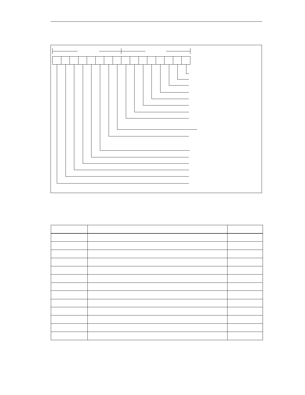
1514131211109876543210
High byte Low byte
1 = Ready to start
1 = Ready to operate
1 = Operation Enabled
1 = Drive fault present
0 = OFF2 (Coast stop command present)
0 = OFF3 (Quick stop command present)
1 = Switch-on inhibit
1 = Drive warning present
1 = Not used (always 1)
1 = Serial operation allowed
0 = Serial operation blocked -
local operation only
1 = Frequency reached
0 = Frequency not reached
1 = Converter output is clockwise
1 = Converter output is counter-clockwise
Future - this may not always be zero
Future - this may not always be zero
Future - this may not always be zero
Figure 11-4 Status Bits for Standard Status Word and Main Feedback
Table 11-3 Operands and Data Types for the DRV_CTRL Subroutine
Inputs/Outputs
Operands Data Types
RUN I, Q, M, S, SM, T, C, V, L, Power Flow BOOL
OFF2 I, Q, M, S, SM, T, C, V, L, Power Flow BOOL
OFF3 I, Q, M, S, SM, T, C, V, L, Power Flow BOOL
F_ACK I, Q, M, S, SM, T, C, V, L, Power Flow BOOL
DIR I, Q, M, S, SM, T, C, V, L, Power Flow BOOL
DRIVE VB, IB, QB, MB, SB, SMB, LB, AC, Constant, *VD, *AC, *LD BYTE
SPD_SP VD, ID, QD, MD, SD, SMD, LD, AC, *VD, *AC, *LD, Constant REAL
RSP_R I, Q, M, S, SM, T, C, V, L BOOL
ERR VB, IB, QB, MB, SB, SMB, LB, AC, *VD, *AC, *LD BYTE
STATUS VW, T, C, IW, QW, SW, MW, SMW, LW, AC, AQW, *VD, *AC, *LD WORD
SPEED VD, ID, QD, MD, SD, SMD, LD, AC, *VD, *AC, *LD REAL
RUN_EN I, Q, M, S, SM, T, C, V, L BOOL
DIR_CW I, Q, M, S, SM, T, C, V, L BOOL

 Loading...


