Conventions for S7-200 Instructions
8-6
S7-200 Programmable Controller System Manual
A5E00066097-02
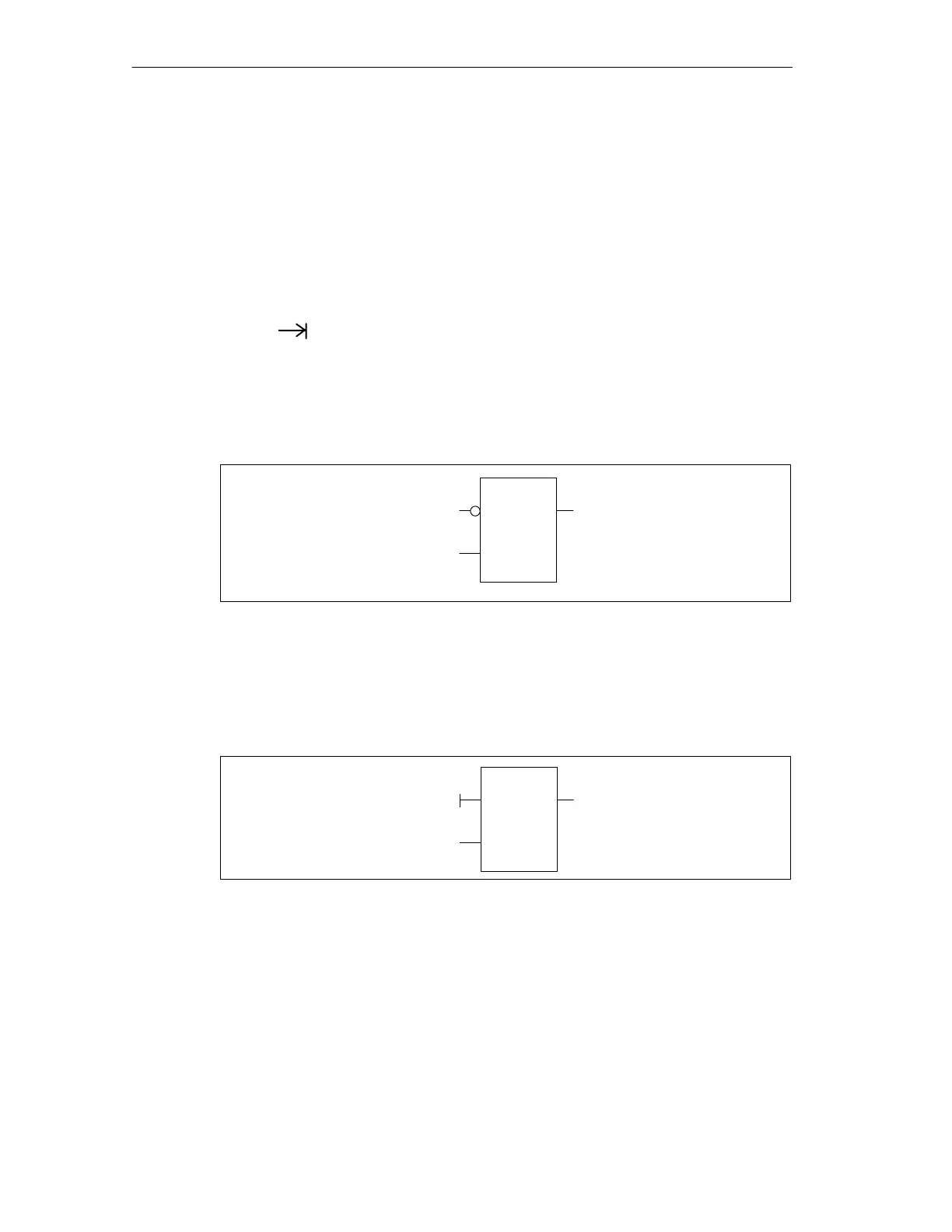
• The logical NOT condition of the state of the operand or power flow driving the
input is shown by the small circle on the input to an FBD instruction. In
Figure 8-2, Q0.0 is equal to the NOT of I0.0 AND I0.1.
Function Block Conventions: In the FBD editor, you can use the F4, F6, and F9
keys on your keyboard to access AND, OR and box instructions. The following
conventions are used in the Ladder Logic editor.
• The ladder editor symbol “--->>” on an EN operand is a powerflow or operand
indicator. It can also depict an open circuit, or required power flow connection.
• The indicates that the output is an optional powerflow for an instruction
that can be cascaded or connected in series.
• Negation bubbles: The logical NOT condition or inverted condition of the
operand or power flow is shown by the small circle on the input. In Figure 8-2,
Q0.0 is equal to the NOT of I0.0 AND I0.1. Negation bubbles are only valid for
Boolean signals, which can be specified as parameters or powerflow.
AND
I0.0
I0.1
Q0.0
Figure 8-2 FBD Diagram of the Logical NOT Condition
• Immediate indicators: The immediate condition of of a Boolean operand is
shown by the vertical line on the input to an FBD instruction (Figure 8-3). The
immediate indicator causes an immediate read from the specified physical
input. Immediate operators are only valid for physical inputs.
AND
I0.0
I0.1
Q0.0
Figure 8-3 FBD Diagram of the Immediate Condition
• Tab key: The tab key moves the cursor from one input to another. The input
currently selected becomes red. Movement is circular beginning with the first
input through the output.
• Box with no input: A box with no input or output indicates an instruction that is
independent of powerflow (Figure 8-1).
• Operand tics: The number of operands can be expanded up to 32 inputs for
AND and OR instructions. To add or subtract operand tics, use the “+” and “-”
keys on your keyboard.

 Loading...


