Installing an S7-200 PLC
2-19
S7-200 Programmable Controller System Manual
A5E00066097-02
Calculating a Sample Power Requirement
Table 2-1 shows a sample calculation of the power requirements for an S7-200
Micro PLC that includes the following:
• CPU 224 AC/DC/Relay
• 3 each EM 223 8 DC In/8 Relay Out
• 1 each EM 221 8 DC In
This installation has a total of 46 inputs and 34 outputs.
The CPU in this example provides sufficient 5 VDC current for the expansion
modules, but does not provide enough 24 VDC current from the sensor supply for
all of the inputs and expansion relay coils. The I/O requires 400 mA and the CPU
provides only 280 mA. This installation requires an additional source of at least
120 mA at 24 VDC power to operate all the included 24 VDC inputs and outputs.
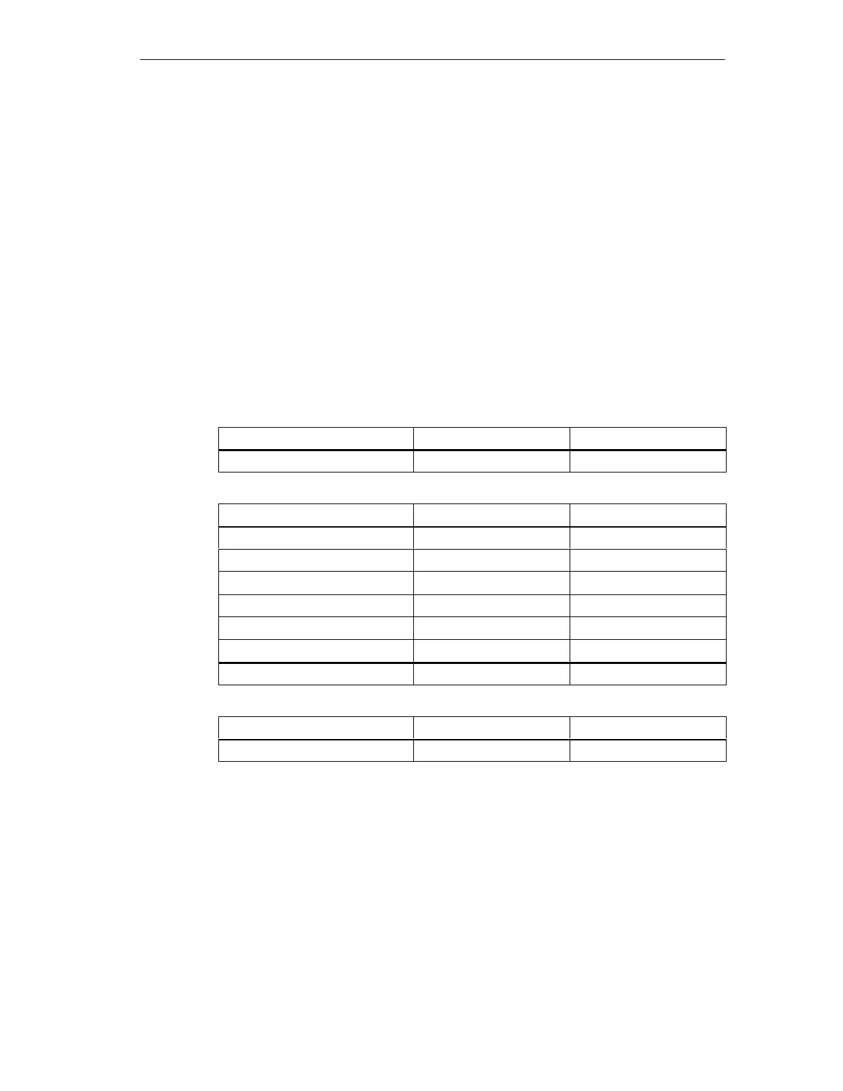
Table 2-1 Power Budget Calculations for a Sample Configuration
CPU Power Budget
5 VDC 24 VDC
CPU 224 AC/DC/Relay 660 mA 280 mA
minus
System Requirements
5 VDC 24 VDC
CPU 224, 14 inputs 14 * 4 mA = 56 mA
3 EM 223, 5 V power required 3 * 80 mA = 240 mA
1 EM 221, 5V power required 1 * 30 mA = 30 mA
3 EM 223, 8 inputs each 3 * 8 * 4 mA = 96 mA
3 EM 223, 8 relay coils each 3 * 8 * 9 mA = 216 mA
1 EM 221, 8 inputs each 8 * 4 mA = 32 mA
Total Requirements 270 mA 400 mA
equals
Current Balance
5 VDC 24 VDC
Current Balance Total 390 mA [120 mA]

 Loading...


