SIMATIC Instructions
9-4
S7-200 Programmable Controller System Manual
A5E00066097-02
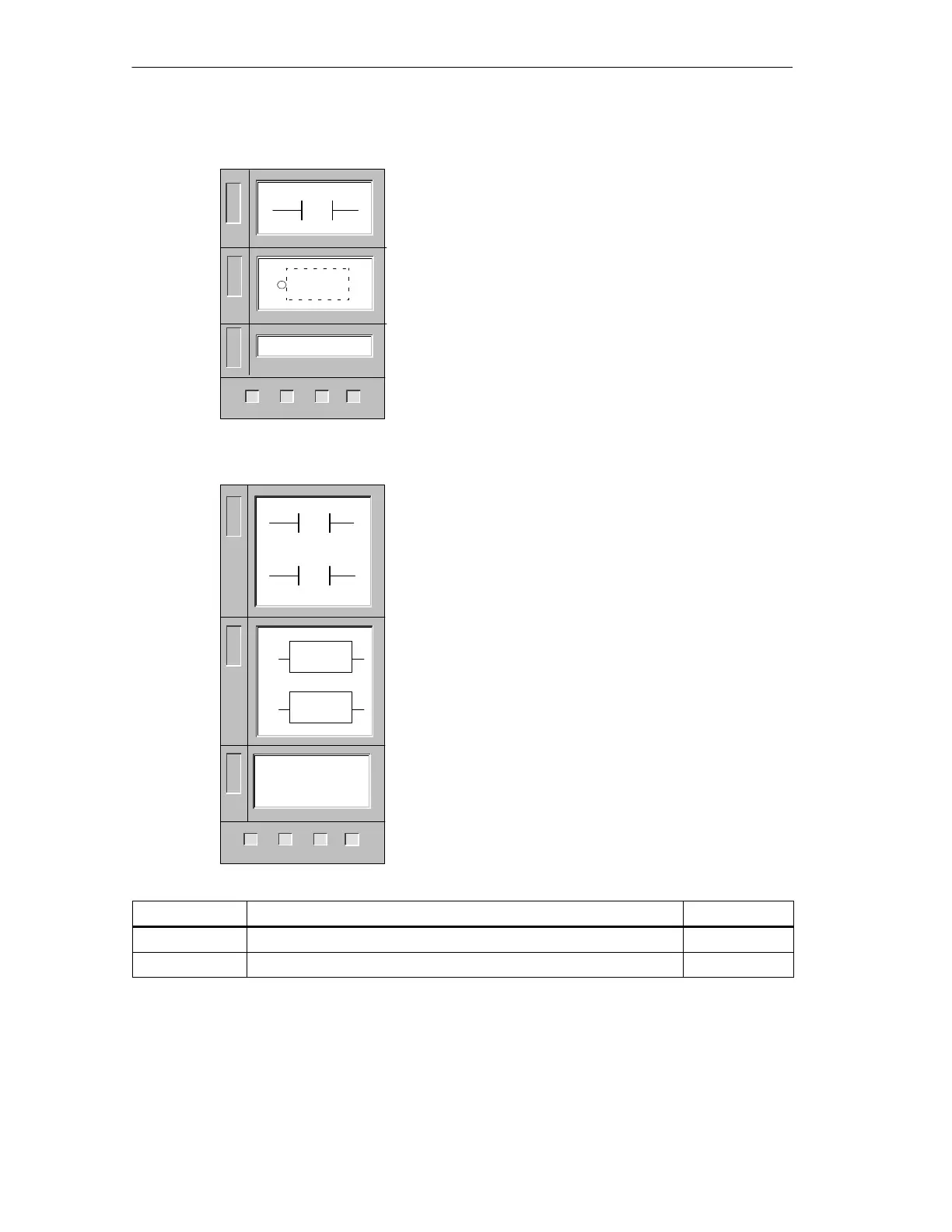
Not
The NOT contact changes the state of power flow input.
When power flow reaches the Not contact, it stops.
When power flow does not reach the Not contact, it
supplies power flow.
In LAD, the NOT instruction is shown as a contact.
In FBD, the NOT instruction uses the graphical negation
symbol with Boolean box inputs.
In STL, the NOT instruction changes the value on the top
of the stack from 0 to 1, or from 1 to 0.
Operands: None
Data Types: None
Positive, Negative Transition
The Positive Transition contact allows power to flow for
one scan for each off-to-on transition.
The Negative Transition contact allows power to flow
for one scan for each on-to-off transition.
In LAD, the Positive and Negative Transition instructions
are represented by contacts.
In FBD, the instructions are represented by the P and N
boxes.
In STL, the Positive Transition contact is represented by
the Edge Up instruction. Upon detection of a 0-to-1
transition in the value on the top of the stack, the top of
the stack value is set to 1; otherwise, it is set to 0.
In STL, the Negative Transition contact is represented by
the Edge Down instruction. Upon detection of a 1-to-0
transition in the value on the top of the stack, the top of
the stack value is set to 1; otherwise, it is set to 0.
Inputs/Outputs Operands Data Types
IN (FBD) I, Q, M, SM, T, C, V, S, L, Power Flow BOOL
OUT (FBD) I, Q, M, SM, T, C, V, S, L, Power Flow BOOL
L
A
D
NOT
NOT
222 224
✓✓✓
221
S
T
L
F
B
D
L
A
D
226
✓
P
N
EU
ED
P
N
222 224
✓✓✓
221
L
A
D
S
T
L
F
B
D
226
✓

 Loading...


