Installing an S7-200 PLC
2-2
S7-200 Programmable Controller System Manual
A5E00066097-02
2.1 Panel Layout Considerations
Installation Configuration
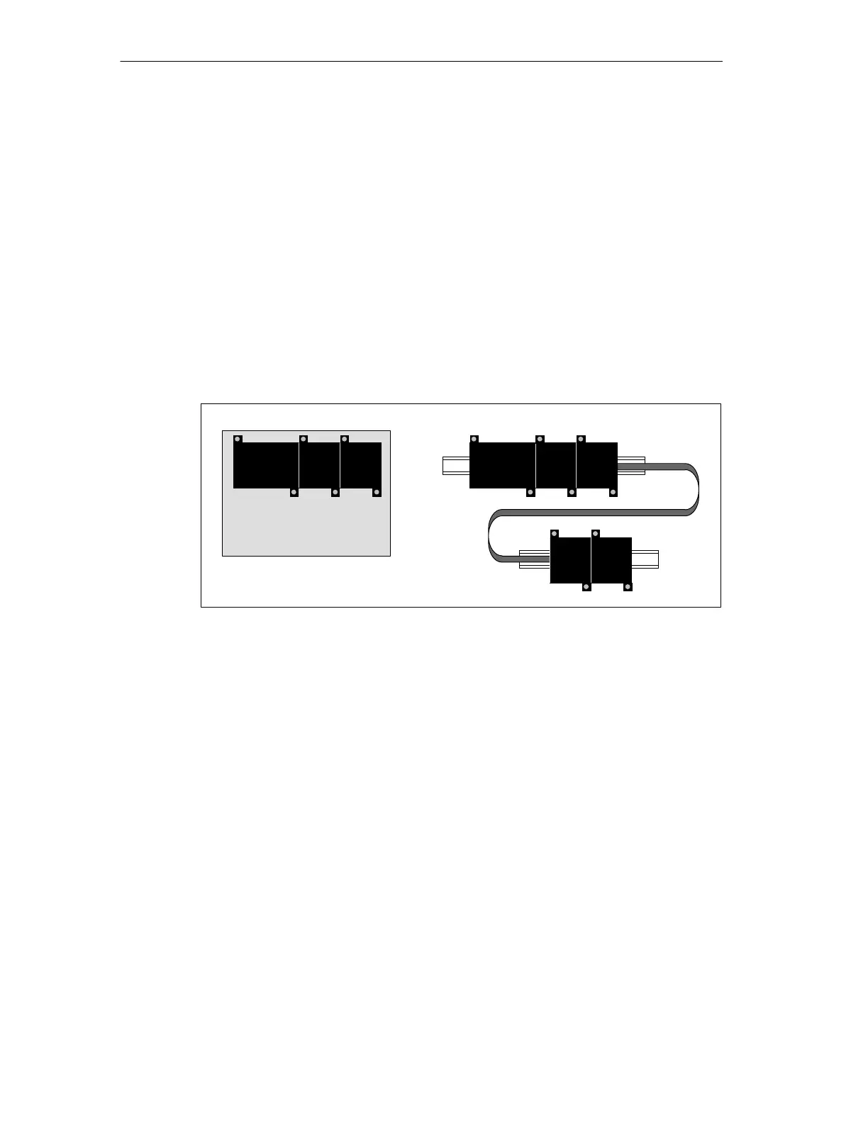
You can install an S7-200 either on a panel or on a standard rail. You can mount
the S7-200 either horizontally or vertically. You can connect the S7-200 to
expansion modules by one of these methods:
• A flexible ribbon cable with mating connector is built into the I/O module for
easy connection to the PLC or another expansion module.
• An I/O expansion cable is also available to add flexibility to your mounting
configuration.
Figure 2-1 shows a typical configuration for these types of installations.
S7-200 I/O I/O
Panel mounting Standard rail mounting
S7-200 I/O I/O
I/O I/O
Figure 2-1 Mounting Configurations
Clearance Requirements for Installing an S7-200 PLC
Use the following guidelines as you plan your installation:
• The S7-200 CPU and expansion modules are designed for natural convection
cooling. You must provide a clearance of at least 25 mm (1 in.), both above and
below the units, for proper cooling. See Figure 2-2. Continuous operation of all
electronic products at maximum ambient temperature and load reduces their
life.
• For vertical mounting, the maximum ambient temperature is reduced by 10° C.
The CPU should be mounted below any expansion modules. If you are
mounting on a vertical DIN rail, you should use the DIN rail stop.
• Allow 75 mm (3 in.) for mounting depth. See Figure 2-2.
• Be sure to allow enough space in your mounting design to accommodate the
I/O wiring and communication cable connections.

 Loading...


