Basic Concepts for Programming an S7-200 CPU
4-32
S7-200 Programmable Controller System Manual
A5E00066097-02
Displaying the Status of the Program in Ladder Logic
You can monitor the status of the ladder program by using STEP 7-Micro/WIN 32.
STEP 7-Micro/WIN 32 must be displaying ladder logic. Ladder status displays the
status of all instruction operand values. See Figure 4-17. All status is based upon
the value of these elements that are read at the end of a CPU scan cycle.
STEP 7-Micro/WIN 32 acquires the values for the status display across multiple
PLC scan cycles and then updates the ladder status screen display. Consequently,
the ladder status display does not reflect the actual status of each ladder element
of the time of execution.
You can use the Options Tool to configure the status screen. Select Tools >
Options and then select the LAD Status tab. Table 4-13 shows the LAD status
display options.
To open the LAD status window, select the status icon from the toolbar
(Figure 4-17).
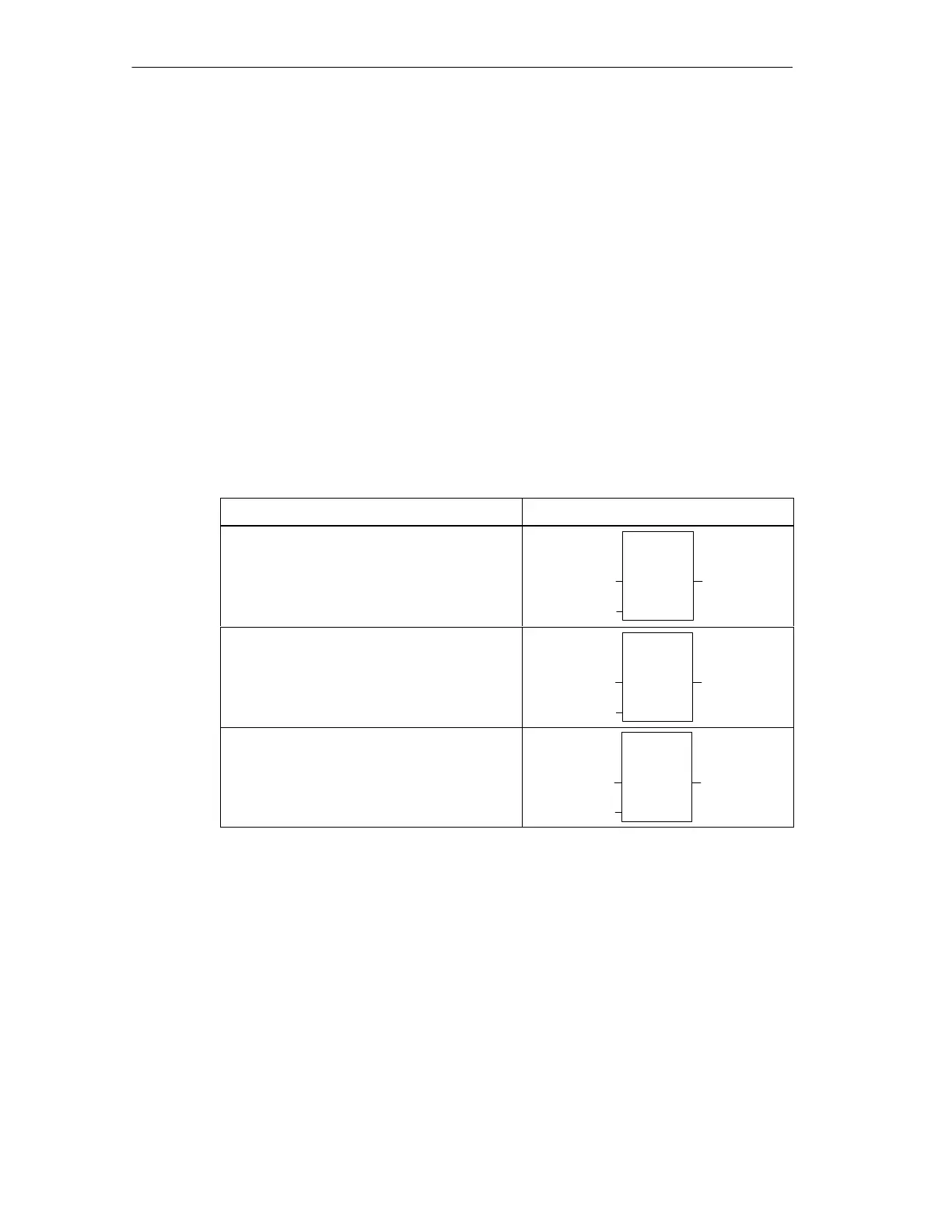
Table 4-13 Selecting Display Options for LAD Status
Display Option LAD Status Display
Show the address inside the instruction
and the value outside the instruction.
OUT
ADD_I
EN
VW0
VW2
VW4
ENO
+777
+23
+800
Show the address and value outside the
instruction.
OUT
ADD_I
EN
IN1
IN2
OUT
ENO
+777=VW0
+23=VW2
+800=VW4
Show only the status value.
OUT
ADD_I
EN
IN1
IN2
OUT
ENO
+777
+23
+800

 Loading...


