SIMATIC Instructions
9-100
S7-200 Programmable Controller System Manual
A5E00066097-02
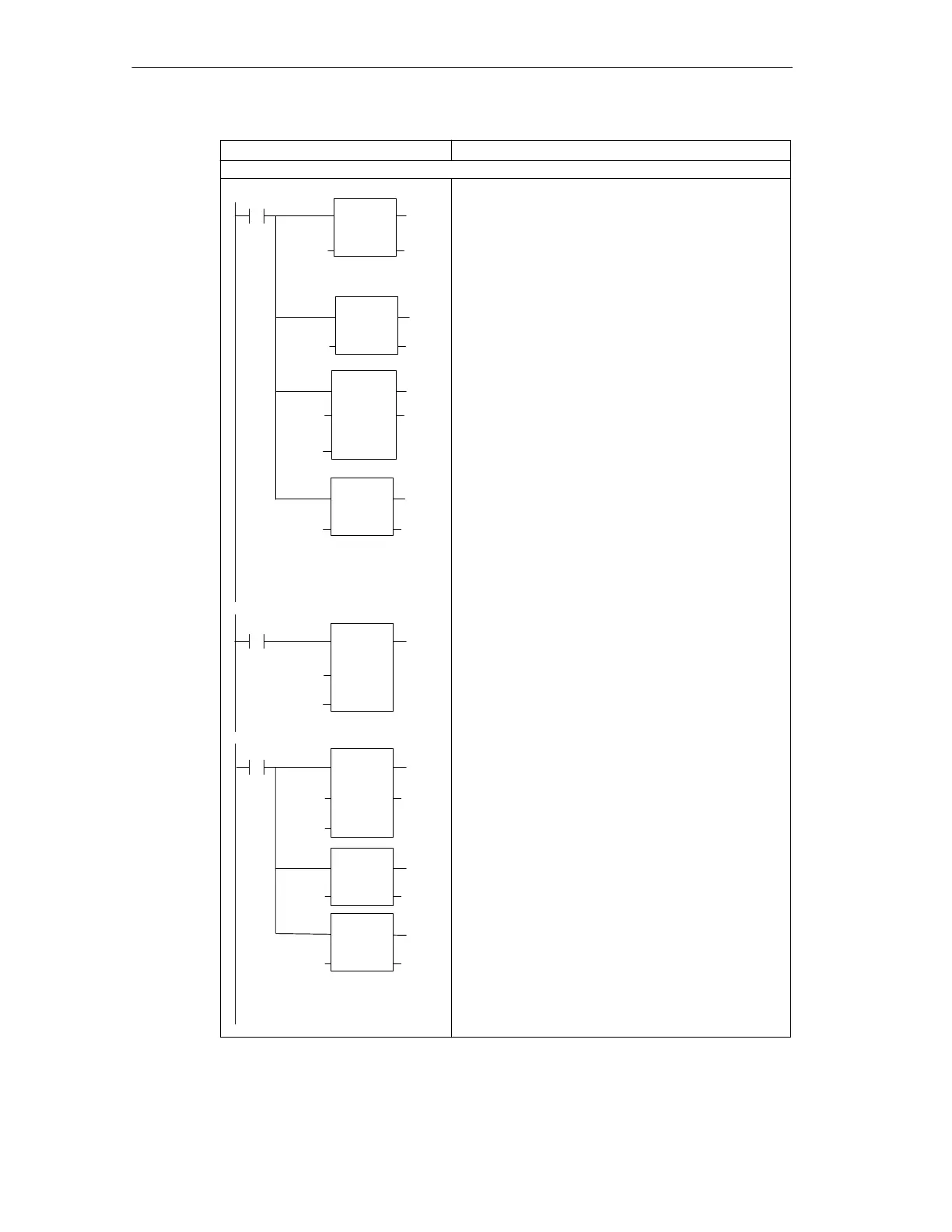
LAD STL
NETWORK 1
//Convert PV to a
//normalized real
//number value - PV is
//a unipolar input and
//cannot be negative.
LD SM0.0
ITD AIW0, AC0 //Save the unipolar
//analog value in
//the accumulator.
DTR AC0, AC0 //Convert the 32-bit
//integer to a real
//number.
/R 32000.0, AC0 //Normalize the value
//in the
//accumulator.
MOVR AC0, VD100 //Store the normalized
//PV in the loop TABLE.
NETWORK 2
//Execute the loop when
//placed in auto mode.
LD I0.0 //When auto mode is
//entered,
PID VB100, 0 //invoke PID execution.
NETWORK 3
//Convert M
n
to a scaled,
//sixteen-bit integer.
//M
n
is a unipolar value
//and cannot be negative.
LD SM0.0
MOVR VD108, AC //Move the loop output
//to the accumulator.
*R 32000.0, AC0 //Scale the value in
//the accumulator.
ROUND AC0, AC0 //Convert the real
//number value to
//a 32-bit integer.
DTI AC0, AQW0 //Write the 16-bit
//integer value to
//the analog output.
//end of Interrupt
Routine 0
I0.0
Network 1
Network 2
ROUND
EN
IN OUT
I_DI
EN
IN OUT
DI_R
EN
IN OUT
DIV_R
EN
IN1
IN2
OUT
PID
EN
TBL
LOOP
MOV_R
EN
IN
OUT
SM0.0
Network 3
SM0.0
OUT
MUL_R
EN
IN1
IN2
OUT
DI_I
EN
IN OUT
AC0
32000
AC0
AIW0
AC0
AC0 AC0
AC0 VD100
VB100
0
VD108
32000
AC0
AC0 AC0
AC0 AQW0
ENO
ENO
ENO
ENO
ENO
ENO
ENO
ENO
INTERRUPT 0
Figure 9-28 Example of PID Loop Control for SIMATIC LAD, STL, and FBD (continued)

 Loading...


