9.8 Configuring SINAMICS S120 with 802D sl
Commissioning
9-102
SINUMERIK 802D sl Instruction Manual (BA), 05/2005 Edition
6FC5 397-0CP10-1BA0
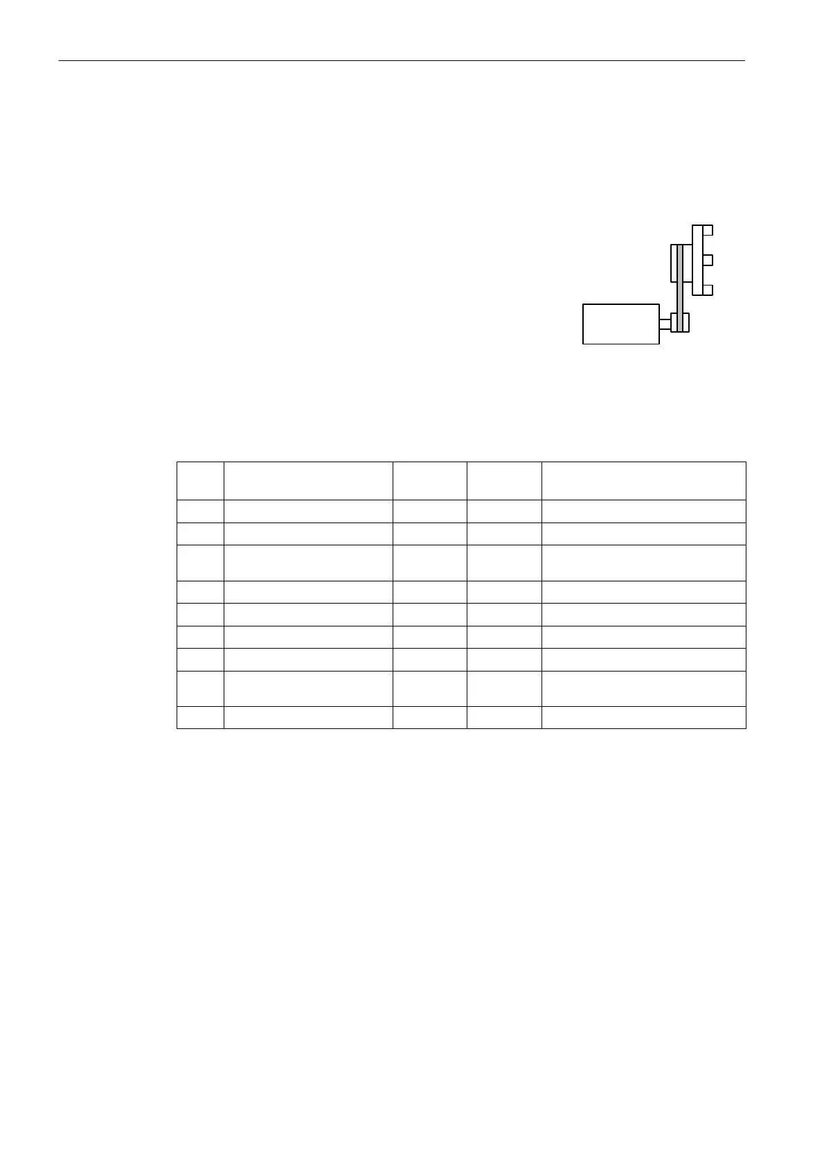
Digital spindle drive with spindle actual-value encoder integrated into the motor
Parameterize the machine data listed in Table 9-8.
Example:
Motor with incremental encoder
Gearbox transmission ratio: 1:2
Max. spindle speed 9,000 r.p.m.
Max. spindle acceleration 60 rev./s
2
Machine data settings:
MD 31030 = 5
MD 31050 = 1
MD 31060 = 2
MD 35130 = 9000
MD 35200 = 60
MD 36200 = 9900
For the spindle, it can be necessary to adapt the following additional machine data.
Table 9-9 Additional machine data
MD
Name Default
value
Unit Recommendation/remark
34000 REFP_CAM_IS_ACTIVE 1 0: without reference point cam
34060 REFP_MAX_MARKER_DIST 20 degrees 720_ = two spindle revolutions
34110 REFP_CYCLE_NR 1 ... 5 0: The spindle is not involved in chan-
nel-specific referencing.
35300 SPIND_POSCTRL_VELO 500 r.p.m.
36000 STOP_LIMIT_COARSE 0,04 degrees 0,4
36010 STOP_LIMIT_FINE 0,01 degrees 0,1
36030 STANDSTILL_POS_TOL 0,2 degrees 1
36060 STANDSTILL_VELO_TOL 0,0139 r.p.m. 1 (interface signal “Axis/spindle
stopped” V390x 0001.4)
36400 CONTOUR_TOL 1 degrees 3
Digital spindle drive with directly mounted spindle actual-value encoder
The operation of a second measuring system requires changes in the message frame type.
To this end, load a reloadable SDB from the toolbox, which allows message frame type 103
for the appropriate drives.
In SINAMICS_I, the message frame type must also be set in P922 = 103.
For the actual-value assignment, the following machine data must be set:

 Loading...


