Interfaces
4.1 CNC operator panel (PCU) interfaces
4-25
SINUMERIK 802D sl Instruction Manual (BA), 05/2005 Edition
6FC5 397-0CP10-1BA0
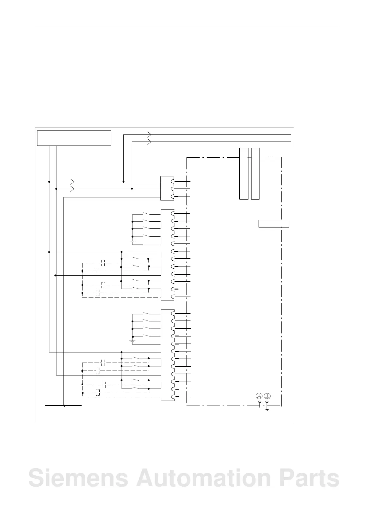
4.1.8 Digital inputs/digital outputs
Various sensors and actuators can be connected to the connectors X20 and X21 via digital
inputs/digital outputs.
Max. 16 or 8 digital inputs and 8 digital outputs can be used.
Wiring diagram and block diagram
PROFIBUS
DRIVE-CLiQ socket 1
X1 X2
CNC operator
panel (PCU)
DRIVE-CLiQ socket 0
X21
X20
24 V DC ext. power supply
X40
P24
M
PE
PE
M
+ 24 V
M
P24
DI1
DI0
DI3
DI2
P24_1
M3
DI/DO1
DI/DO0
DI/DO2
M_1
M_1
DI/DO3
DI5
DI4
DI7
DI6
P24_2
M_4
DI/DO5
DI/DO4
DI/DO6
M_2
M_2
DI/DO7
1
12
P24
M
2
3
4
5
6
7
8
9
10
11
X6
1
12
2
3
4
5
6
7
8
9
10
11
Grounding
1
2
3
Fig. 4-1 Connection example
Siemens Automation Parts

 Loading...


