4.1 CNC operator panel (PCU) interfaces
Interfaces
4-26
SINUMERIK 802D sl Instruction Manual (BA), 05/2005 Edition
6FC5 397-0CP10-1BA0
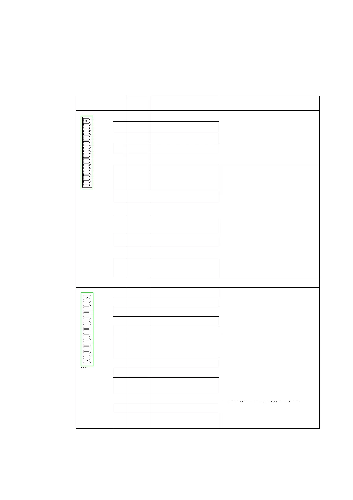
Connector pin assignment
Designation: X30
Type: 12-pin connector
Table 4-6 Pin assignment of the connectors X20 and X21
Schematic
view
Pin Name Description Technical details
1 DI0 Digital input 0 Input:
1
2 DI1 Digital input 1
Voltage: D
24 V
20.4 ... 28.8 V
Level:
3 DI2 Digital input 2
0 signal: –3...5 V
1-si
nal: 11...30 V
4 DI3 Digital input 3
...
Input delay:
0 → 1 signal: 15 ms (typ 6)
5 M_3 Ground for DI0...DI3
→
s
gna
:
ms
yp.
1 → 0 signal: 150 ms (typically 40)
12
6 P24_1 DC 24 V Supply voltage for
DI/DO0...DI/DO3 (required
for digital outputs)
For the output:
max. output current:
1 signal: 5 mA ... 0.5 A
Total current of all outputs:
X20
7 DI/DO0 Digital I/O
max. 2 A (in case of simultaneous occur-
8 DI/DO1 Digital I/O
Output delay:
9 M_1 Ground for DI/DO0...DI/
DO3
→
:
m
(typ. 150 ms)
1 → 0 signal: 500 ms
10 DI/DO2 Digital I/O
yp.
ms
each with RL = 60 ohms
11 DI/DO3 Digital I/O
w
c
ng
requency:
100 Hz (ohmic load)
12 M_1 Ground for DI/DO0...DI/
DO3
z
n
uct
ve
oa
For the input:
Data see connector X21
1 DI4 Digital input 4 Input:
1
2 DI5 Digital input 5
for the data, see connector X20
3 DI6 Digital input 6
4 DI7 Digital input 7
5 M_4 Ground for DI4...DI7
6 P24_2 DC 24 V Supply voltage for
DI/DO4...DI/DO7 (required
for digital outputs)
Output:
for the data, see connector X20
Input:
12
7 DI/DO4 Digital I/O
Voltage: DC 24 V (20.4 ... 28.8 V)
X21
8 DI/DO5 Digital I/O
eve
:
0 signal: –3...5 V
9 M_2 Ground for DI/DO4...DI/
DO7
1 signal: 11...30 V
Input delay:
0 → 1 signal: 15 ms (typ 6)
10 DI/DO6 Digital I/O
→
s
gna
:
ms
yp.
1 → 0 signal: 150 ms (typically 40)
11 DI/DO7 Digital I/O
12 M_2 Ground for DI/DO4...DI/
DO7

 Loading...


