Ionics Instruments 2004 Page D - 3 DLM 30007-08 Rev. A
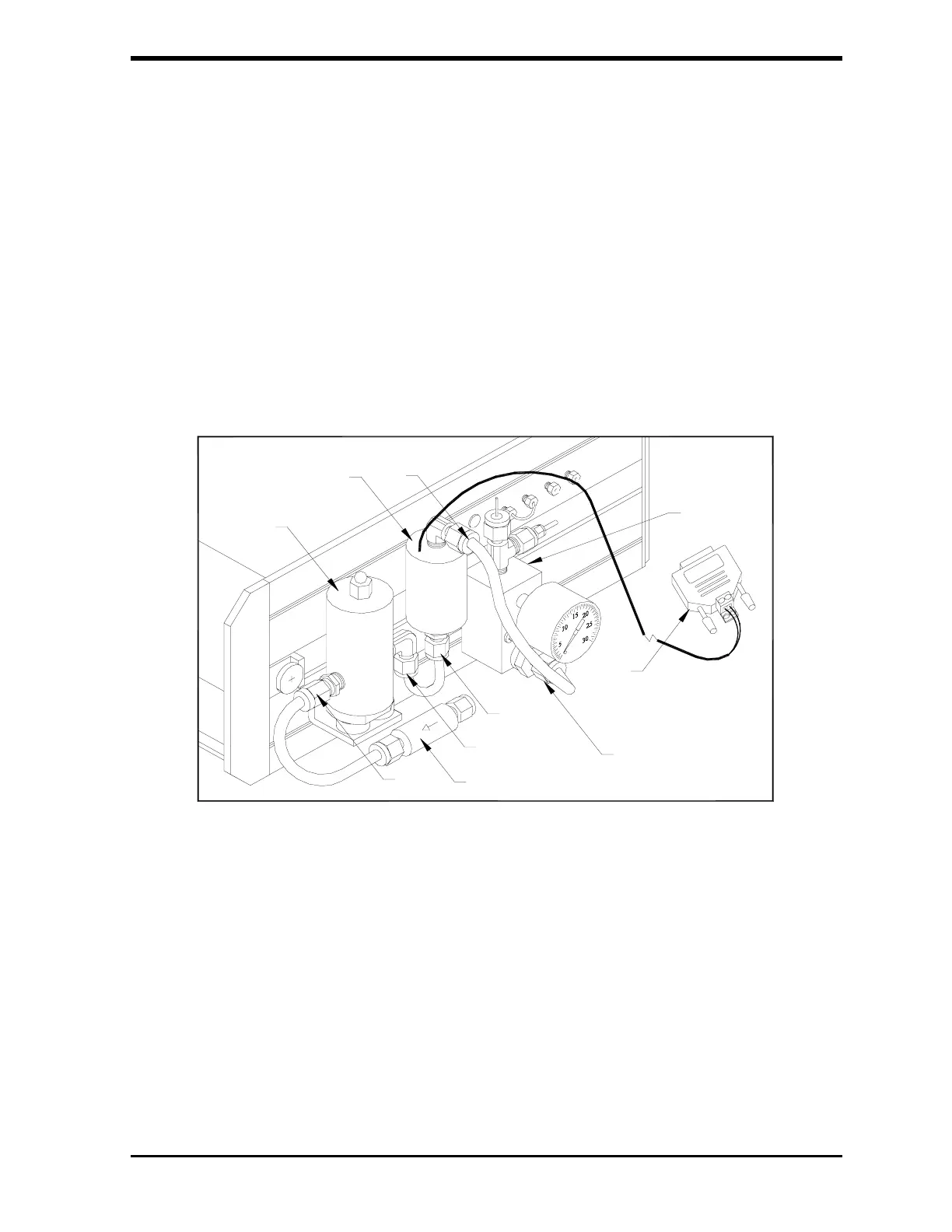
6. Position the flow switch and secure the end of the stainless steel U-
tube to the regulator outlet. Wires must point up to have a calibrated
normally open switch.
7. Secure the PFA tube from the outlet of the switch to the inlet of the
sampling block.
8. Connect the wires from the flow switch to the Binary Input Module,
polarity is not important to the binary module.
9. Route the electrical cable as desired and plug the end into the AUX
PORT on the opposite side of the analyzer.
FIGURE D-2: Installed Flow Switch