Ionics Instruments 2004 Page D - 2 DLM 30007-08 Rev. A
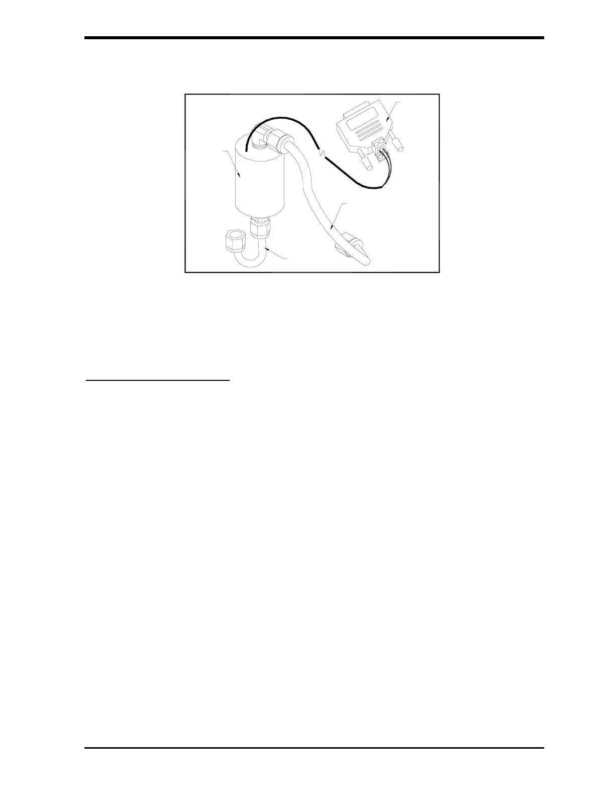
FIGURE D-1: Flow Switch Kit
Mechanical Installation
(Refer to Figures D-1 and D-2 for this procedure. Reference will depend on
orientation of tubing from regulator.)
1. Remove the outlet PFA tube connector from the pressure regulator of
the analyzer.
2. Detach the regulator from the analyzer by removing the two screws
on the bottom of the mounting bracket, making sure not to lose the
fiber spacers.
3. Remove the elbow from the outlet side of the regulator and clean the
port and connector threads of any Teflon tape that remains. Reapply
4 wraps of Teflon tape to the elbow and screw the fitting back into the
regulator ending with the tube fitting pointing down as shown.
4. Reinstall the regulator to the analyzer with the two screws making
sure to use the fiber spacers.
5. Remove the PFA tube from the inlet of the sampling block.
FLOW
SWITCH
STAINLESS
STEEL
TUBING
PFA
TUBING
BINARY
INPUT
MODULE