Ionics Instruments 2004 Page 4-9 DLM 30007-08 Rev. A
AUX
AC
TERMINAL STRIP
Power
ON/OFF
SWITCH
ALARM 1 ALARM 2 4-20 mA V OUT
PARALLEL PRINTER PORT
AUX PORT
RS-232 PORT
NC
COM
NO
NC
COM
NO
POS
NEG
+10V
+IV
-V
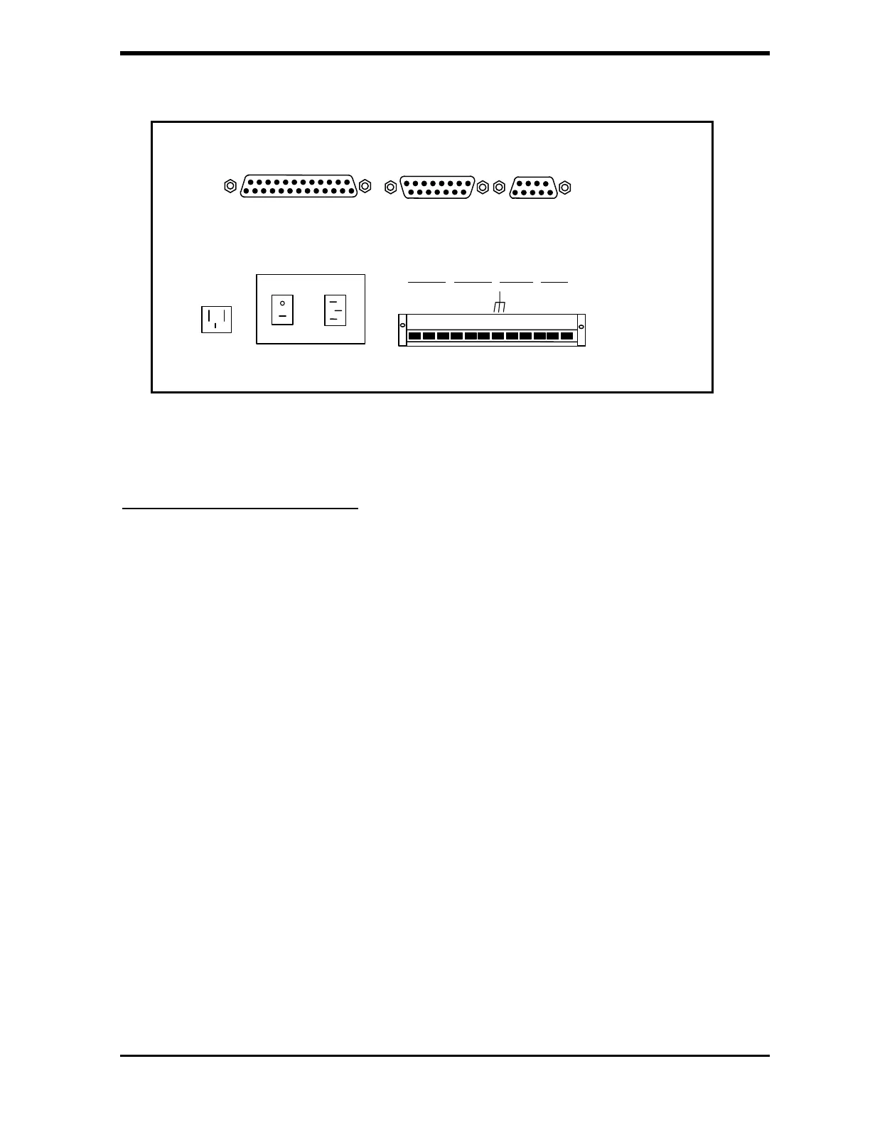
FIGURE 4-5: Output Connectors for the 820 TOC Analyzer
Recorder and Alarm Outputs
The data from the analyzer can be recorded using a 4–20 mA or 0–10 V
recorder, and two alarms can be used. The recorder and alarm outputs are
selected from the terminal strip and must be configured as described in this
chapter. The outputs of the terminal strip are in Table 1. Only one recorder
output (4-20 mA, 0-1 V or 0-10 V) could be used at a time. The output is
calibrated and set for 4-20 mA when shipped. The position of a jumper in the
analyzer must be changed to select the 0-1 V recorder output.
The maximum load for the 4-20 mA port is 400 ohms and it has a 12 V loop
supply with a compliance to 10 V. The interface to the data collection system
should be either a differential input or an otherwise isolated input. The 4-20
mA circuit return is to the system circuit ground and it should not have a large
common mode voltage applied to it. The maximum load for the alarm ports is
1A, 30 VDC or 0.5 A, 125VAC.