Ionics Instruments 2004 Page 4-8 DLM 30007-08 Rev. A
Electrical
Installing the Recorder, Alarm, and Printer Cables - Wiring
The output connectors are located on the left-hand side of the analyzer (see
Figures 4-4 & 4-5). The long green connector is a terminal strip for the analog
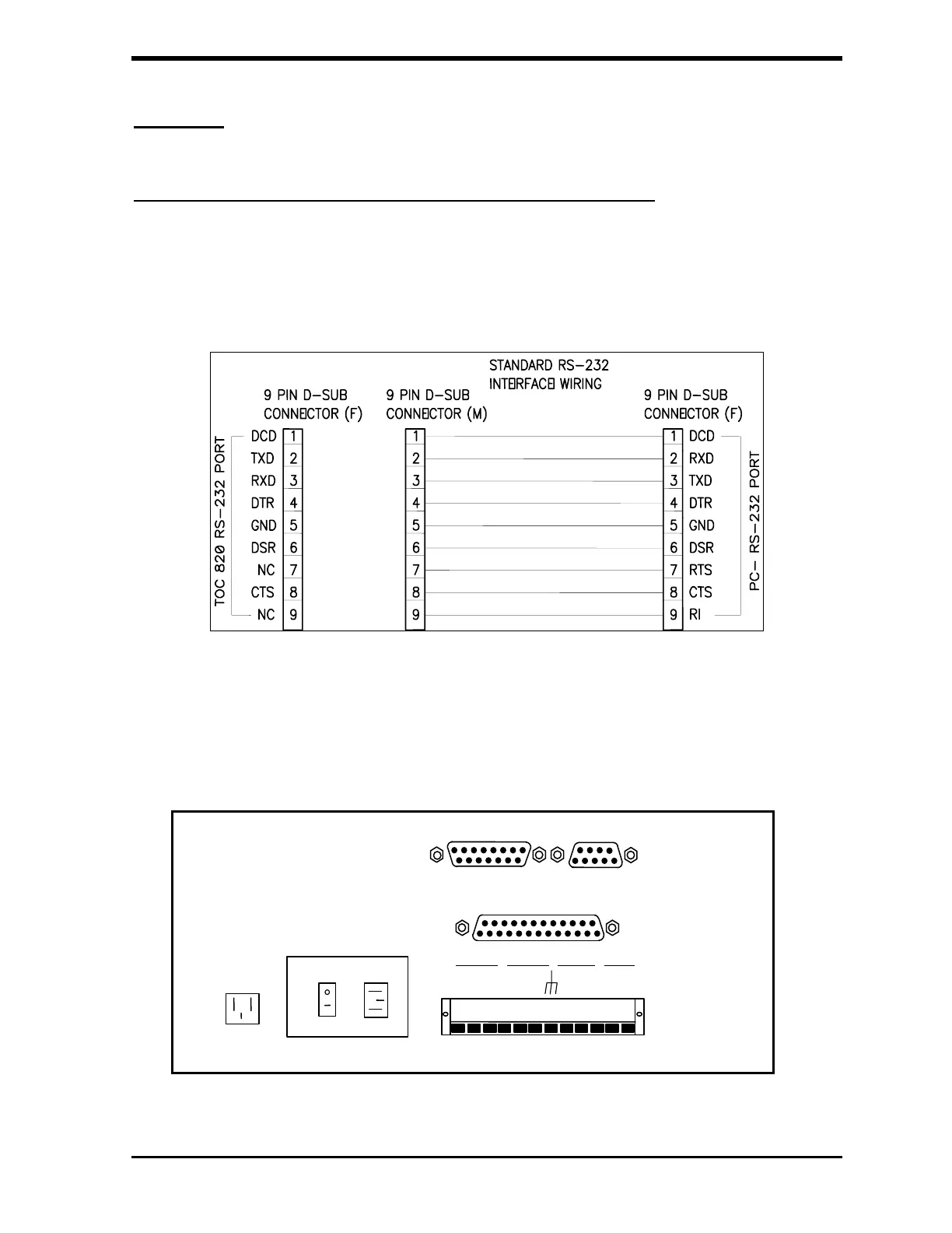
and alarm outputs. The parallel printer output is the 25-pin female connector
and the 9-pin female is the RS-232 computer output.
FIGURE 4-3: TOC STANDARD RS-232 9 Pin D-sub
The 15-pin auxiliary port connector is used for the autosampler option. See
Appendix B for CE Mark Specifications. The AUX AC connector carries the
line voltage and is used to power accessories for the analyzer.
UX
C
TERMINAL STRI
Power
ON/OFF
SWITCH
ALARM 1
ALARM 2 4-20 mA V OUT
PARALLEL PRINTER PORT
AUX PORT
RS-232 PORT
NC
CO
NO
NC
COM
NO
POS
NEG
+10V
+IV
-V
FIGURE 4-4: Output Connectors for the 800/810 Analyzer