Ionics Instruments 2004 Page 4-10 DLM 30007-08 Rev. A
Table 1. Analog Outputs on Terminal Strip
Pin Number (from left) Output
1 Alarm 0 (NC*)
2 Alarm 0 (Common)
3 Alarm 0 (NO**)
4 Alarm 1 (NC*)
5 Alarm 1 (Common)
6 Alarm 1 (NO**)
7 Not used
8 4–20 mA (+ Output)
9 4–20 mA (- Output)
10
Voltage Output (+10 or +1 V)
***
11 Voltage Output (Ground)
12 Not Used
* NC - normally closed
** NO - normally open
*** Voltage range selected by jumper
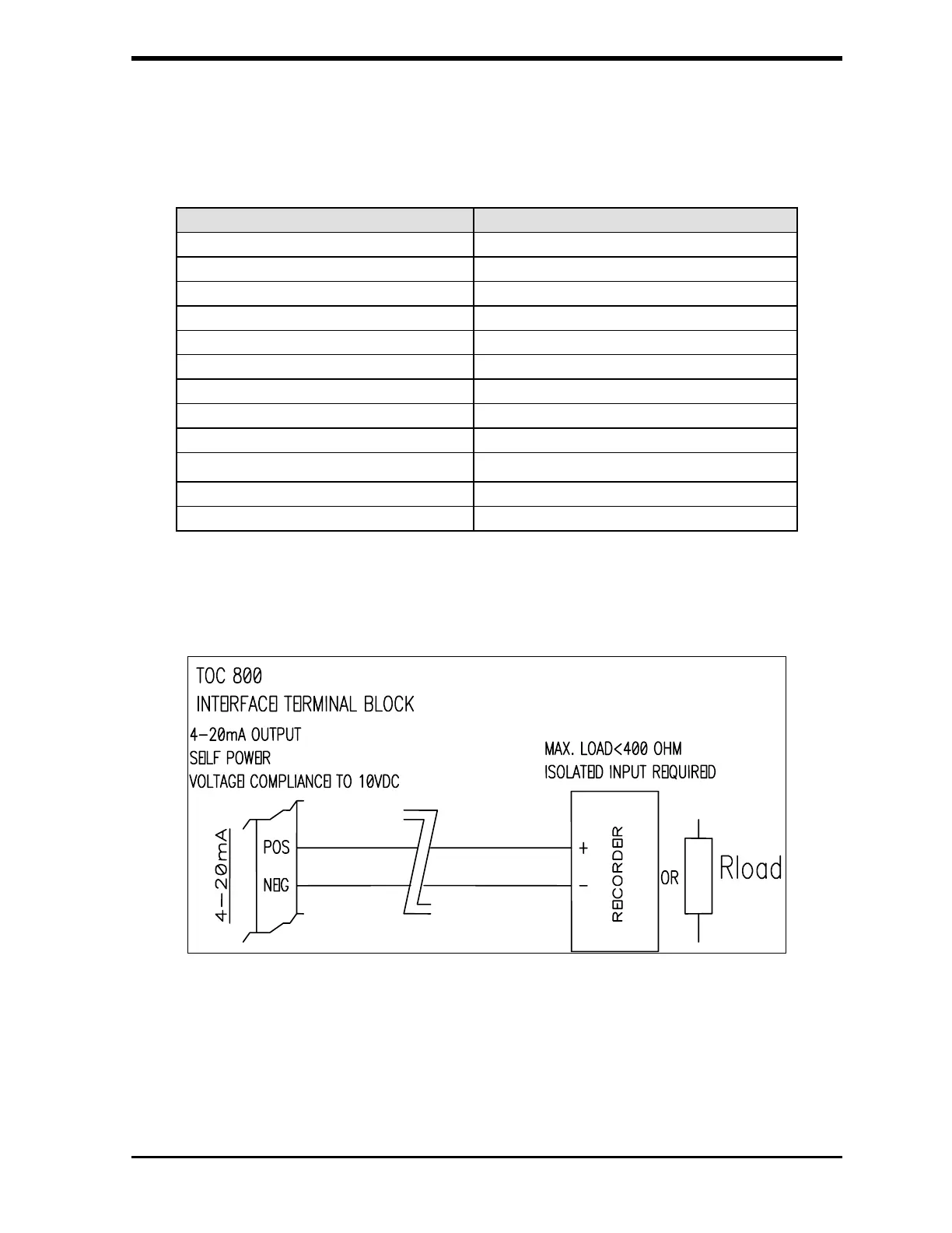
FIGURE 4-6: Typical 4-20 mA Output Wiring Diagram
Turn off the main power to the analyzer before connecting the alarm and
recorder outputs. Connect the appropriate wires to the recorder or alarm, and
then connect the wires to the terminal strip.