Section 04 ENGINE MANAGEMENT (SDI)
Subsection 03 (COMPONENT INSPECTION, REPLACEMENT AND ADJUSTMENT)
Refer to TEMPERATURE SENSOR TABLE at the
beginning of this section to find the corresponding
resistance value for this sensor temperature.
Recheck also resistance value between terminals
11 and 27 on ECM connector A. This resistance is
used for ECM.
Refer to TEMPERATURE SENSOR TABLE at the
beginning of this section to find the corresponding
resistance value for this sensor temperature.
If resistance value is correct, try a new ECM. Re-
fer to ENGINE CONTROL MODULE (ECM) in this
section.
If resistance value is incorrect, repair the connec-
tors or replace the wiring harness between ECM
connector and the CTS.
Replacement
Drain cooling system.
Disconnect CTS connector and remove CTS.
Apply Loctite 5910 on the new CTS and torque to
12 N•m(106lbf•in).
Reinstall remaining removed parts.
Refill engine coolant and bleed cooling system.
Refer to LIQUID COOLING SYSTEM section.
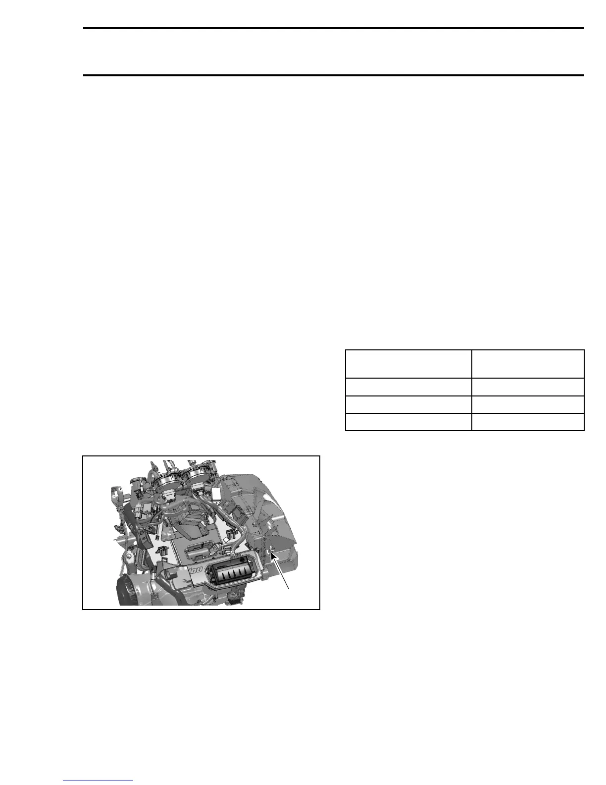
AIR PRESSURE SENSOR (APS)
A35C3SE
1
INSIDE LH SIDE PANEL
1. Air pressure sensor (APS)
Ensure sensor is correctly installed on air intake si-
lencer. Otherwise, the APS could generate a fault
code. Remove sensor and check for oil or dirt on
its end and if problem persists, check the wiring
harness. Perform the following tests.
Voltage Test
Check the voltage output from ECM to the APS.
Install the tether cord cap, turn OFF engine cut-out
switch and push START/RER button momentarily
to activate the ECM.
Disconnect plug connector from APS and connect
a voltmeter between terminal 1 and 2 of wiring
harness.
Voltageshouldbe5V.
Check the continuity between terminal 3 on APS
connector and terminal 18 on ECM connector.
If tests are good, replace the APS.
If tests are not good, continue to check the conti-
nuity of the rest of the APS circuit on the harness.
Disconnect the connector “A” from the ECM.
Using a multimeter, check continuity of circuits as
per following table.
CIRCUIT NUMBER
(ECM CONNECTOR “A”)
APS CONNECTOR
A-3 TERMINAL 1
A-4 TERMINAL 2
A-18 TERMINAL 3
If wiring harness is good, try a new ECM. Refer to
ENGINE CONTROL MODULE (ECM) in this sec-
tion.
Otherwise, repair the connectors or replace the
wiring harness between ECM connector and the
APS.
Replacement
Disconnect APS connector and remove the APS.
The ATS is retained with a screw.
Install the new APS.
mmr2005-126 153