Section05ELECTRICALSYSTEM
Subsection 05 (ACCESSORIES AND LIGHTING SYSTEM)
Continuity Test
Remove the relay from vehicle.
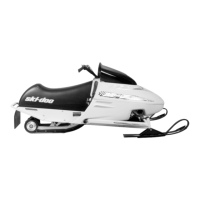
Using the multimeter FLUKE 111 (P/N 529 035
868), select the beeper position.
A33E1JA
Position the RED probe on the terminal 30 and the
BLACK probe on the terminal 87a.
A33E1KA
1
2
1. Terminal 30
2. Terminal 87a
A continuous signal should be audible. If not, re-
place the relay.
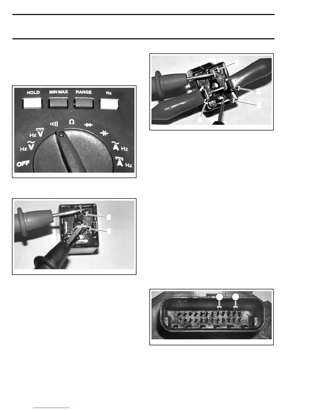
If a signal is audible, apply 12 volts on terminals
85and86thenplacetheREDprobeonterminal
30 and the BLACK on the terminal 87.
A33E1LA
1
3
2
4
1. Terminal 30
2. Terminal 87
3. Terminal 85
4. Terminal 86
The continuous signal should be audible. If not,
replace the relay.
SPEEDOMETER
Removal
Insert a little flat screwdriver into the slot at the
bottom of the speedometer. Slightly, pry the
speedometer and turn it clockwise then remove
it from accessories panel.
Unplug connector.
Tes t
No Lights and the Needle Does Not Move
Remove the speedometer. Apply 12 volts be-
tween pin 8 and pin 11. Place the positive probe
onpin8andthenegativeonpin11.
NOTE: Respect positive and negative positions if
not the speedometer could be damaged.
A35E02A
8 11
If the speedometer stays off, change it.
If the speedometer is lighted, check connector
and wiring harness. Repair defective parts.
182 mmr2005-130