Section 06 DRIVE SYSTEM
Subsection 02 (DRIVE PULLEY)
GENERAL
WARNING
Never use any type of impact wrench at drive
pulley removal and installation. The use of
impact wrench could damage the drive pulley
and modify the calibration.
Some drive pulley components (return spring,
ramp) can be changed to improve vehicle perfor-
mance in high altitude regions. A service bulletin
will give information about calibration according
to altitude.
CAUTION: Such modifications should only be
performed by experienced mechanics since
they can greatly affect vehicle performance.
Verify spring specifications before installation.
Do not only refer to the spring color code.
NOTE: TRA drive pulley stands for Total Range
Adjustable drive pulley.
WARNING
Any drive pulley repairs must be performed
by an authorized Ski-Doo dealer. Subcompo-
nent installation and assembly tolerances re-
quire strict adherence to procedures detailed.
Ring Gear
Each time the drive pulley is removed from the
engine, check the tightening of ring gear screws.
Torque them if necessary.
CAUTION: All 995 engines are equipped with
a ring gear, even though the vehicle does not
have an electric starter. The ring gear is used
as a damper. Do not remove it.
REMOVAL
Remove drive belt.
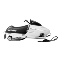
Secure drive pulley no. 1 with the drive pulley
holder (P/N 529 035 674). Install it over a sliding
half tower.
A32D1WC
529 035 674
TYPICAL — INSERT THE TOOL IN SLIDING FLANGE TOWER
Remove the drive pulley bolt no. 2 and its conical
spring washer no. 3.
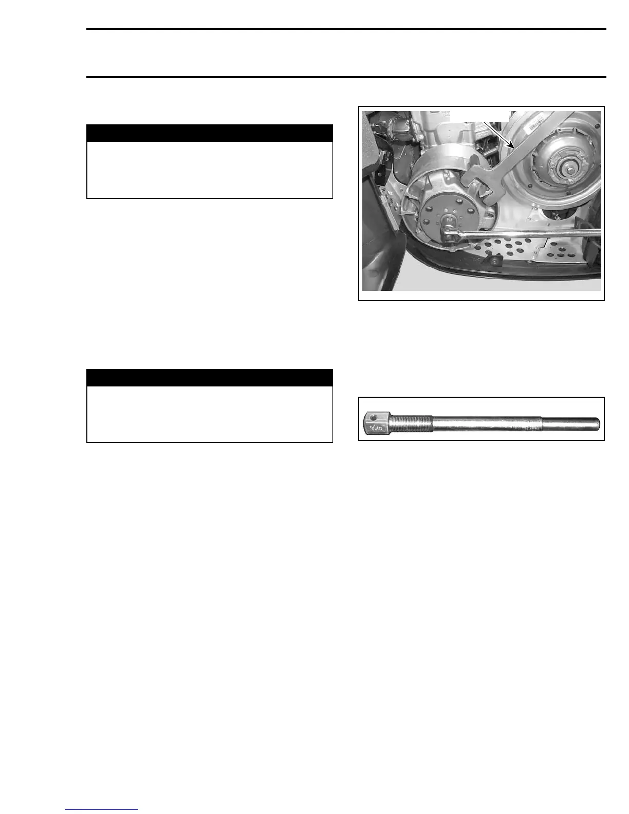
To remove drive pulley no. 1 and/or fixed half no. 4
from engine, use the drive pulley puller (P/N 529
022 400).
529 022 400
Retain drive pulley with the drive pulley holder
(P/N 529 035 674), and install the puller in pulley
shaft then tighten.
CAUTION: These pulleys have metric threads.
Do not use imperial threads puller. Always
tighten puller by hand to ensure that the drive
pulleyhasthesametypeofthreads(metricvs
imperial) prior to fully tightening.
DISASSEMBLY
Ring Gear
To remove the ring gear no. 5, use a heat gun to
break the threadlocker on ring gear screws no. 6
before disassembly.
CAUTION: If another tool than a heat gun is
used, do not exceed 150°C(300°F).
Fixed Half
CAUTION: NEVER tap on governor cup no. 7.
mmr2005-132 191