Section05ELECTRICALSYSTEM
Subsection 02 (CHARGING SYSTEM)
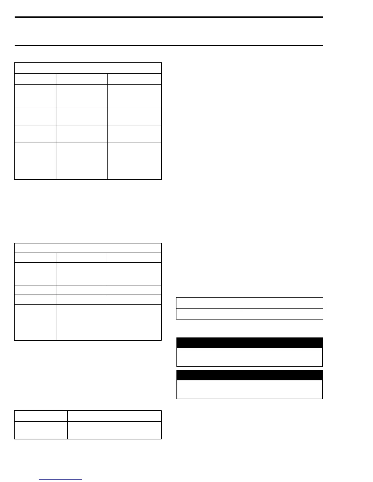
STATOR
TEST
Output Coil insulation
TEST
PROBES
YELLOW,
YELLOW and
GREEN
YELLOW and
ENGINE
RESISTANCE
00.0 to 00.5
3times
O.L.
VOLTAGE
3.5to5.5
3times
—
NOTE
Do the test
between A and
B,AandCand
BandCusing
manual starter
Engine refers to
the engine parts
connected to the
magneto housing.
VOLTAGE REGULATOR/
RECTIFIER
Te s t
To test the voltage regulator/rectifier use the fol-
lowing table.
VOLTAGE REGULATOR/RECTIFIER
TEST
Charging voltage Current to battery
TEST
PROBES
RED/GREEN and
negative battery
terminal
RED and
RED/WHITE
RESISTANCE
— —
VOLTAGE
Battery voltage 2to4A
NOTE
—
Engine @ 5000 RPM
with fully charged
battery. With 30 A
fuse removed and
ammeter in series.
If the voltage regulator/rectifier is within the spec-
ification, the wiring harness between the voltage
regulator/rectifier and battery is defective. If the
voltage regulator/rectifier is out of specification
and the stator tests good, the voltage regula-
tor/rectifier is defective.
Removal
MODEL LOCATION
All models of
RT series
Under engine and behind muffler
All Models
Disconnect battery.
Remove muffler.
Unplug all connectors located on connector sup-
port.
Remove nuts that attach the voltage regulator/rec-
tifier to the frame.
Installation
The installation is the reverse of the removal pro-
cedure. Pay attention to the following.
Removetherubberplugunderframetogainac-
cess to install the nut on PTO side. Install this nut
first.
Torque voltage regulator/rectifier nuts to 10 N•m
(89 lbf•in).
BATTERY
NOTE: For manual start models with a small
battery/capacitor arrangement, refer to ENGINE
MANAGEMENT SECTION.
General
Sealed valve regulated lead acid (VRLA) battery
are used. They are non-spillable and maintenance
reduced — no electrolyte level to be checked and
readjusted. No ventilation tube is attached to the
battery.
SUPPLIER P/N BRP P/N
YTX20L-BS
410 301 203
Removal
WARNING
Battery BLACK (–) cable must always be dis-
connected first and connected last.
WARNING
Never charge or boost battery while installed
on vehicle.
Open right side panel of vehicle.
Disconnect BLACK (–) cable end from the termi-
nal.
166 mmr2005-128