Section 05 ELECTRICAL SYSTEM
Subsection 05 (ACCESSORIES AND LIGHTING SYSTEM)
ACCESSORIES AND LIGHTING SYSTEM
SERVICE TOOLS
Description Part Number Page
multimeter FLUKE 111 ......................................................... 529 035 868
......................... 178, 182–184
supply cable..........................................................................
529 035 997
................................. 177, 183
supply harness......................................................................
529 035 869
......................... 177–178, 183
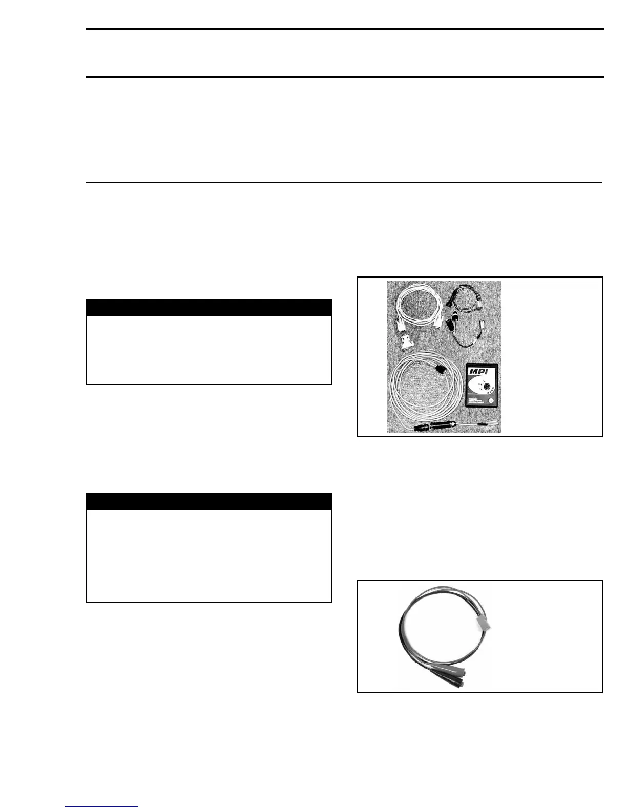
VCK (Vehicle Communication Kit).........................................
529 035 981 ......................................... 177
GENERAL
WARNING
It is recommended to always disconnect the
battery when replacing any electric or elec-
tronic parts. Always disconnect battery ex-
actly in the specified order, BLACK (-) cable
first. Do not place tools on battery.
During assembly/installation, use the torque val-
ues and service products as in the exploded
views.
Clean threads before applying a threadlocker. Re-
fer to SELF-LOCKING FASTENERS and LOCTITE
APPLICATION at the beginning of this manual for
complete procedure.
WARNING
Torque wrench tightening specifications
must be strictly be adhered to. Locking de-
vices (e.g.: locking tabs, elastic stop nuts,
self-locking fasteners, cotter pins, etc.) must
be installed or replaced with new ones where
specified. If the efficiency of a locking device
is impaired, it must be renewed.
Lighting and Accessories System
Te s t in g
Connect the VCK (Vehicle Communication Kit)
(P/N 529 035 981).
529 035 981
In BUDS, click on the relay 2 (R2) button to supply
lighting system with 12 volts.
To supply 12 volts to the accessories, click on the
relay 3 (R3) button.
Once this test is done, disconnect the VCK.
Connect the supply cable (P/N 529 035 997) to the
supply harness (P/N 529 035 869).
CAUTION: Respect polarity by connecting 12V
to RED wire and ground to BLACK wire.
529 035 997
mmr2005-130 177