Section 06 DRIVE SYSTEM
Subsection 03 (DRIVEN PULLEY)
GENERAL
During assembly/installation, use the torque val-
ues and the service products as in the exploded
views.
Clean threads before applying a threadlocker. Re-
fer to SELF-LOCKING FASTENERS and LOCTITE
APPLICATION at the beginning of this manual for
complete procedure.
WARNING
Torque wrench tightening specifications
must strictly be adhered to.
Locking devices (e.g.: locking tabs, elastic
stop nuts, self-locking fasteners, cotter pins,
etc.) must be installed or replaced with new
ones where specified. If the efficiency of
a locking device is impaired, it must be re-
newed.
WARNING
Never start engine when the pulley guard is
removed.
WARNING
The driven pulley is a precisely balanced unit.
Never replace parts with used parts from an-
other driven pulley.
REMOVAL
Driven Pulley
Remove belt guard and drive belt.
Remove driven pulley bolt no. 1 and shouldered
washer no. 2 then pull the driven pulley no. 3 from
the countershaft.
Countershaft and Countershaft Bearing
To remove and install countershaft and its bearing
refer to CHAINCASE.
DISASSEMBLY
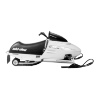
Using the clutch spring compressor (P/N 529 036
012), push the cam no. 4.
A35D11A
2
1
1. Clutch spring compressor
2. Cam
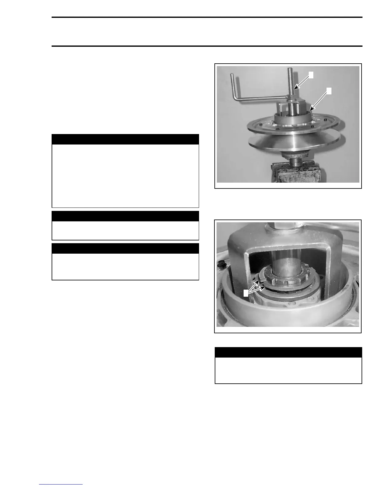
Remove the half keys no. 5.
A35D12A
1
1. Half keys
WARNING
Driven pulley cam is spring loaded, use only
the above mentioned tool. Do not use other
clutch spring compressor.
Unscrew clutch spring compressor then remove
cam and spring no. 6 andseparatethe2pulley
halves.
Remove the circlip no. 9 and the washer no. 10
then remove the roller no. 7 from the roller axle
no. 11.
mmr2005-133 203