Section05ELECTRICALSYSTEM
Subsection 02 (CHARGING SYSTEM)
Battery Charging
WARNING
Always wear safety glasses and charge in
a ventilated area. Never charge or boost
battery while installed on vehicle. Do not
open the sealed caps during charging. Do
not place battery near open flame.
CAUTION: If battery becomes hot, stop charg-
ing and allow it to cool before continuing.
NOTE: Sealed VRLA batteries have an internal
safety valve. If battery pressure increases due to
overcharging, the valve opens to release excess
pressure, preventing battery damage.
Perform BATTERY CHARGE TESTING above then
proceed as described here.
An automatic charger is the fastest and most con-
venient way for error-proof charging.
When using a constant current charger, charge
battery according to the chart below.
Battery Voltage Below 12.8 V and Above 11.5 V
STANDARD CHARGING
(RECOMMENDED)
BATTERY
TYPE
TIME CHARGE
YTX20L-BS 4–9hours 2A
QUICK CHARGING
BATTERY
TYPE
TIME CHARGE
YTX20L-BS
50 minutes 10 A
Battery Voltage Below 11.5 V
Batteries with voltage below 11.5 V r
equires spe-
cial procedures to recharge. In c
harginganover
discharged battery, its inter
nal resistance may be
toohightochargeatanorma
l charging voltage.
Therefore, it may be nec
essary to raise the volt-
age of the battery ini
tially to 25 V as a maximum,
andchargefo
r approximately 5 minutes.
If the charger ammeter shows no change in cur-
rent after 5 minutes, you need a new battery. Cur-
rent flowing into the battery at high voltage can
become excessive. Monitor amperage and adjust
voltage as necessary to keep current at the bat-
tery’s standard amp rating. Charge for approxi-
mately 20 hours.
Installation
Reinstall battery and secure bracket properly.
Connect RED (+) cable it to positive battery termi-
nal. Connect RED wire (coming from 30 A fuse).
Connect BLACK (–)cableLAST.
WARNING
Battery BLACK (–) cable must always be dis-
connected first and connected last.
WARNING
Never charge or boost battery while installed
on vehicle.
Cover the RED (+) terminal with rubber boot.
Apply silicone dielectric grease (P/N 293 550 004)
on battery posts and connectors.
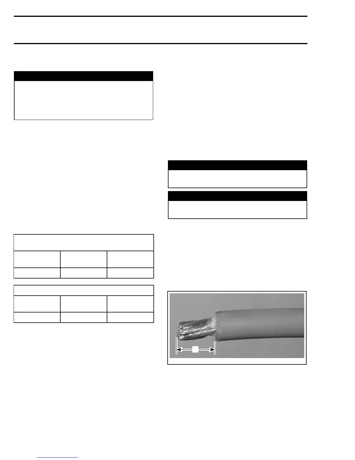
CABLE TERMINAL INSTALLATION
Carefully strip the wire approximately to 10 mm
(1/2 in) in length, using a wire stripping tool or
sharp blade/knife.
A32E2QA
A
A. 10 mm (1/2 in)
NOTE: Make sure not to cut wire strands while
stripping the wire.
Install the appropriate terminal on the wire accord-
ing to the requirement. Refer to appropriate parts
catalog.
168 mmr2005-128