Section 08 STEERING/FRONT SUSPENSION
Subsection 01 (STEERING SYSTEM)
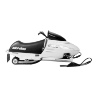
A35I02A
1
FUEL GAUGE
1. Unplug
Remove console.
MachZandSummit
If applicable, cut locking ties retaining harnesses
to steering column no. 1.
Unbolt handlebar ass’y from steering column and
move it aside.
Remove tuned pipe.
Detach the short tie rod no. 8 from the steering
column. Note that a hardened flat washer no. 7
goes on each side of steering column lever.
Disengage carriage bolts no. 5 and no. 6 from
steering column.
Remove plastic U-clamps from steering column.
Pull steering column from top.
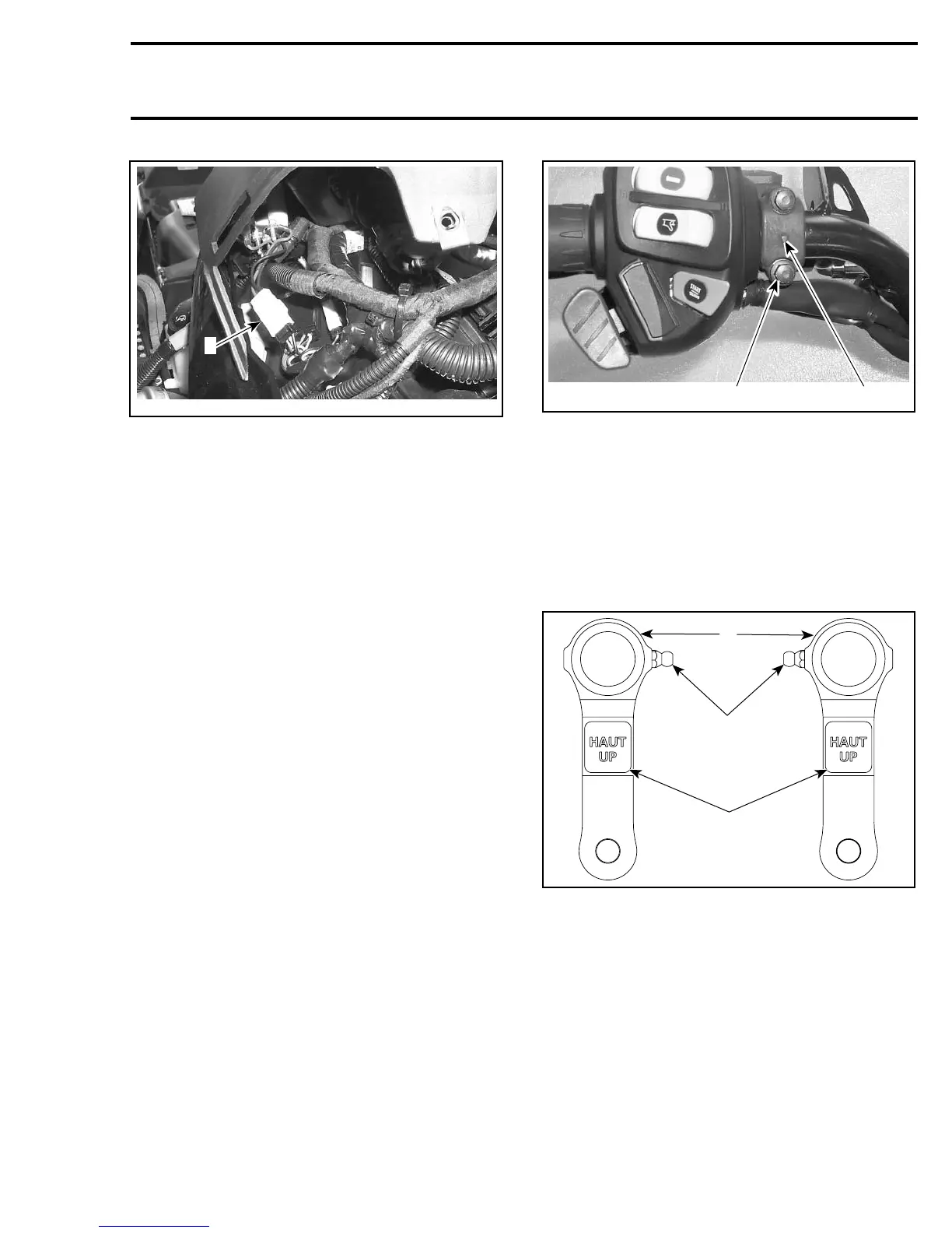
If, for any reason, the master cylinder has been
removed from handlebar note that its clamp
no. 27 must be installed with the embossed ar-
row pointing downward. Torque screws to 8 N•m
(71 lbf•in) beginning with the bottom screw.
1
A33D0ZA
2
1. Arrow on clamp pointing downward
2. Tighten bottom screw first
Refer to HANDLEBAR POSITION ADJUSTMENT
for handlebar reinstallation.
RH and LH Swivel Arm
At assembly respect UP mention.
Grease fitting no. 16 of swivel arms no. 14 must
face toward center of vehicle.
A35G04A
1
3
2
1. UP mention
2. Grease fittings
3. Swivel arms
Ball Joint (left hand and right
hand threads)
The maximum external threaded length not en-
gaged in the tie rod must not exceed 20 mm
(25/32 in).
mmr2005-141 285