DC5 User’s Manual
Setup 1-6
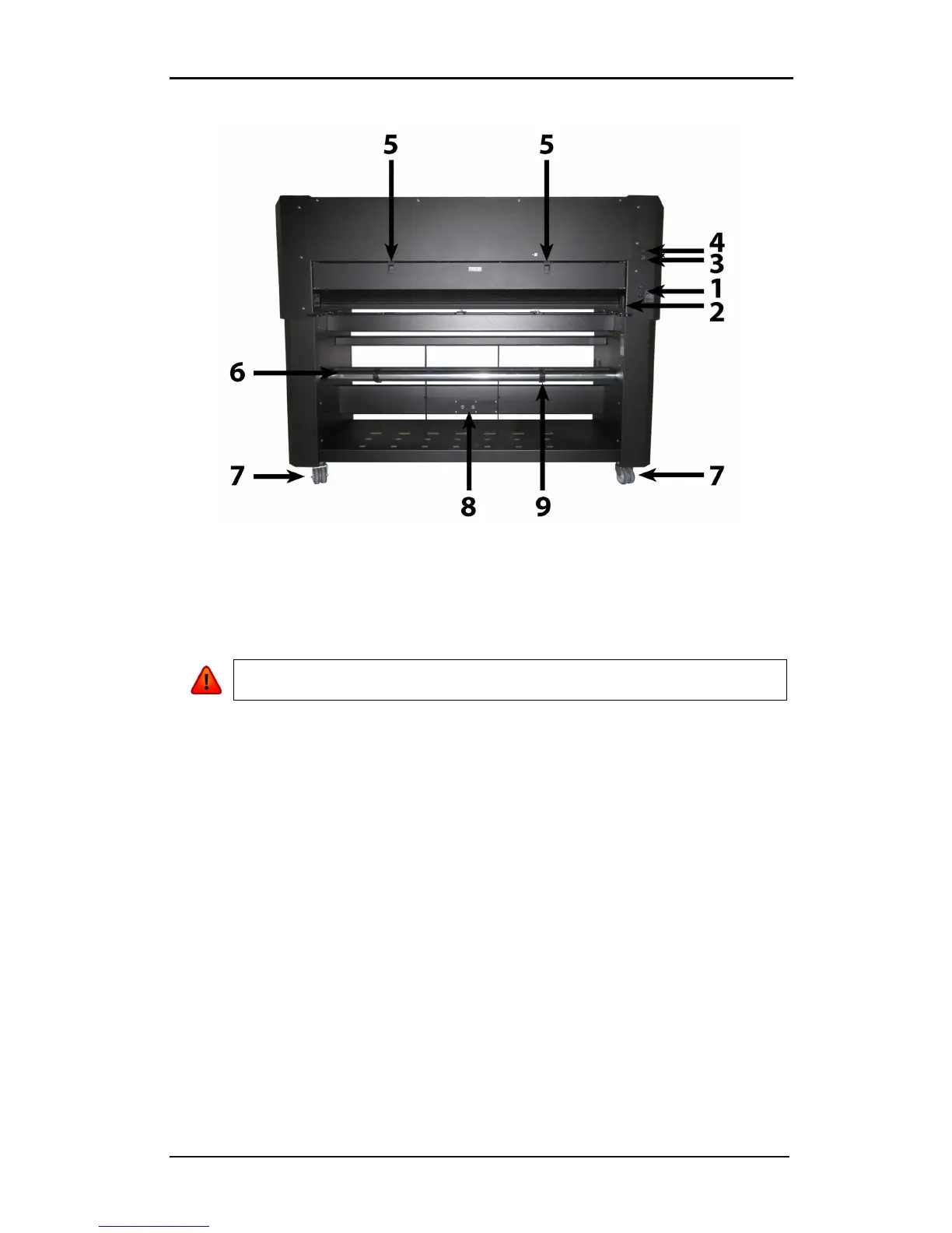
1.2.2 The printer as viewed from the back
FIG 1-7
1-7 DC5(sx), REAR VIEW
1. Power Entry Module: The fuse box, the AC power cord receptacle and the on/off
switch are located in the power entry module. See section 1.4. regarding power up
procedure and section 1.4. regarding information about changing the fuse.
2. Media Load push buttons: On the right side there are two push buttons, conveniently
located to make the loading process easy. For further explanation, see section 1.6.1.
3. Ethernet port RJ45: For connecting the cutter to the LAN.
4. USB port: This interface is based on the standards specified in Universal Serial Bus
Specifications Revision 1.1. It allows for high-speed bi-directional serial communication
between the host computer and the DC5(sx).
5. Cassette station latch: Two latches are located at the back, in order to open up the
cassette station. Open only when the machine is paused or switched off.
6. Media supply rollers: The two back rollers are part of the media supply system.
7. Rear Wheels: The rear wheels of the DC5(sx) have no locking brakes.
8. Media Supply Sensor: The media supply sensor enables the motorized media supply
rollers. - Do not place any objects in front of the sensor.
9. Roll media guide bushes: The two flange guides serve to keep the media roll in place
when media is pulled from the roll. The left one has a fixed position.