Print&Cut 3-1
3 Print & Cut
3.1 Contour cutting
There are two possible ways to contour-cut.
Normally the cutting is done automatically directly after the job is printed. The Rip
recognizes the contour lines, splits up print and cut data, sends the printing data to the
DC5(sx) first and sends the cutting data afterwards.
When the printout has to be laminated, extra registration marks have to be added so the
job can then be cut afterwards.
NOTE: The DC5(sx) can print a protective layer (with the scratch guard ribbon) so
most lamination jobs can done while cutting and can then be cut immediately
after printing. In case the printouts are used in a
harsh chemical, abrasive or
climatologic environment, extra lamination is necessary ( section 3.1.1.2).
3.1.1 Making the design
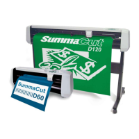
The orientation shown in this figure is the one that will be visible on the computer screen
when the design is created. When the design is exported and printed out with SCC, then the
orientation on the printer is rotated by 180%.
Create the design and contour line. For easier handling, place the contour lines on a
different layer (they will have to be cut out afterwards).
FIG 3-1
3-1 DESIGN WITH CONTOUR
NOTE: When defining contours, do not define them exactly on the border of the
design! It is advised to leave either a white space between the contour and the
design, or to define the contour inside a thick outline. Or better jet, just inside the
design. If the
contour is designed right on the edge of the drawing, then the
slightest misalignment will result in a bad result.