S Class 3 User’s Manual
OPOS 3-3
This parameter, although it is an internal parameter, needs to be set in the Print & Cut
software. The following options are usually available:
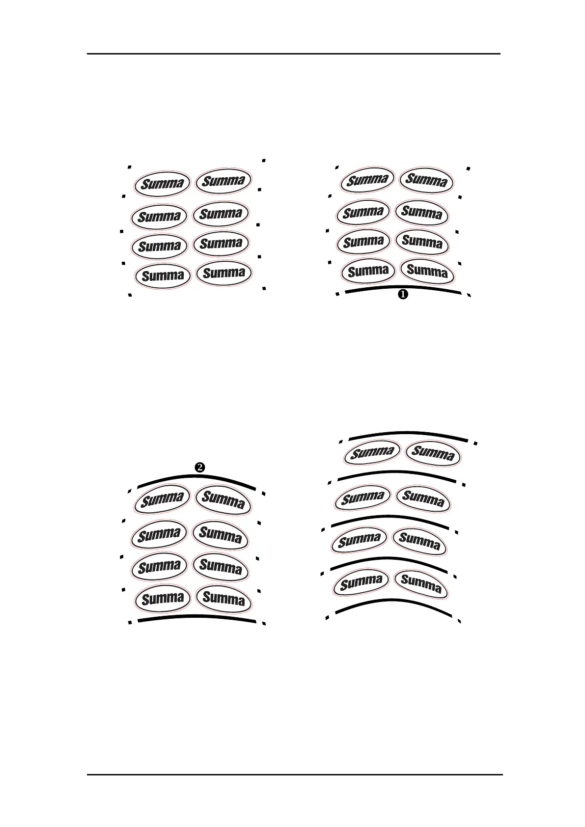
A row of marks is printed at the left and right
side of the graphic. These marks are read by
the OPOS sensor and then used for
compensating printing deformation.
An extra line at the bottom of the job is
printed (line in the figure above), the
sensor reads it and can also compensate for
deformations along the width of the
machine.
Analogue to the bottom XY line, a line (line
in the figure above) is printed at the top
of the job for cutting large jobs more
accurately.
Analogue to the bottom XY line, a line is
printed between each left-right mark.
FIG 3-3
3-3 OPOS ALIGNMENT METHODS
3.2.2 Different OPOS alignment methods