1C-8 Engine Electrical Devices:
Cylinder Temp. Sensor Removal and
Installation
Z9J0111306002
Removal
1) Remove the ring gear cover.
Refer to “Ring Gear Cover Removal and Installation”
in Section 1D (Page 1D-2).
2) Remove the thermostat cover.
Refer to “Thermostat Removal and Installation” in
Section 1F (Page 1F-3).
3) Disconnect the cylinder temp. sensor lead wire
connector.
Loosen and remove the cylinder temp. sensor (1).
Installation
Installation is reverse order of removal.
• Clean mating surface of sensor and cylinder.
• Tighten sensor to specified torque.
Tightening torque
Cylinder temp. sensor (a): 8 N·m (0.8 kgf-m, 5.8
lbf-ft)
• Connect connector to sensor securely.
• Check to ensure that all removed parts are back in
original position.
• Check wire routing.
Refer to “Wiring Harness Routing Diagram” in Section
4A (Page 4A-3).
Cylinder Temp. Sensor Inspection
Z9J0111306003
1) Remove the cylinder temperature sensor.
Refer to “Cylinder Temp. Sensor Removal and
Installation” (Page 1C-8).
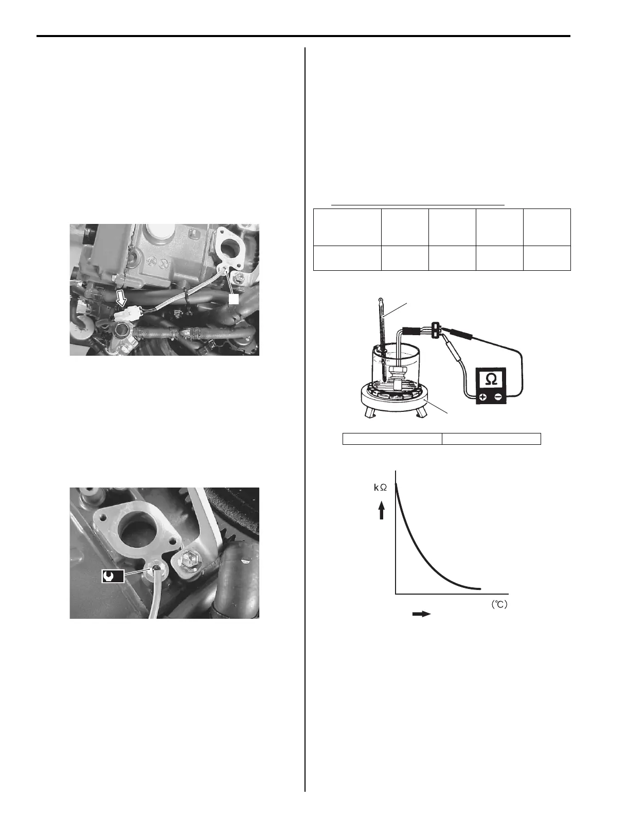
2) Immerse temperature sensing part of cylinder temp.
sensor in water.
3) Measure resistance between sensor terminals while
heating water gradually.
4) If measured resistance does not change in the
proportion indicated, replace sensor.
Cylinder temp. sensor specification
5) Reinstall the cylinder temp. sensor.
Refer to “Cylinder Temp. Sensor Removal and
Installation” (Page 1C-8).
1
I9J011130039-01
(a)
I9J011130040-01
Water
temperature:
°C (°F)
0 (32) 25 (77) 50 (122) 75 (135)
Resistance
(kΩ)
5.3 – 6.6 1.8 – 2.3
0.73 –
0.96
0.33 –
0.45
1. Thermometer 2. Heater
1
2
I9J011130051-01
Temperature
Resistance
I9J011130008-02