3A-6 Right Hand Rotation Unit:
5) Set the clutch control lever (3) at “Neutral” position,
then slide the lower unit (4) into place, ensuring that
the top of driveshaft engages properly with driven
gear shaft and that water tube locates in water pump
case outlet.
NOTE
In order for shift rod and clutch rod splines to
be aligned correctly, clutch rod may need to
be turned slightly right or left.
6) Apply suzuki silicone seal to five gearcase bolts and
tighten them to specified torque.
: Sealant 99000–31120 (SUZUKI Silicone
Seal (50 g))
Tightening torque
Gearcase bolt (a): 55 N·m (5.5 kgf-m, 40.0 lbf-ft)
7) Shift the clutch control lever to “Forward” and
“Reverse” position from “Neutral” position to check
proper gear engagement.
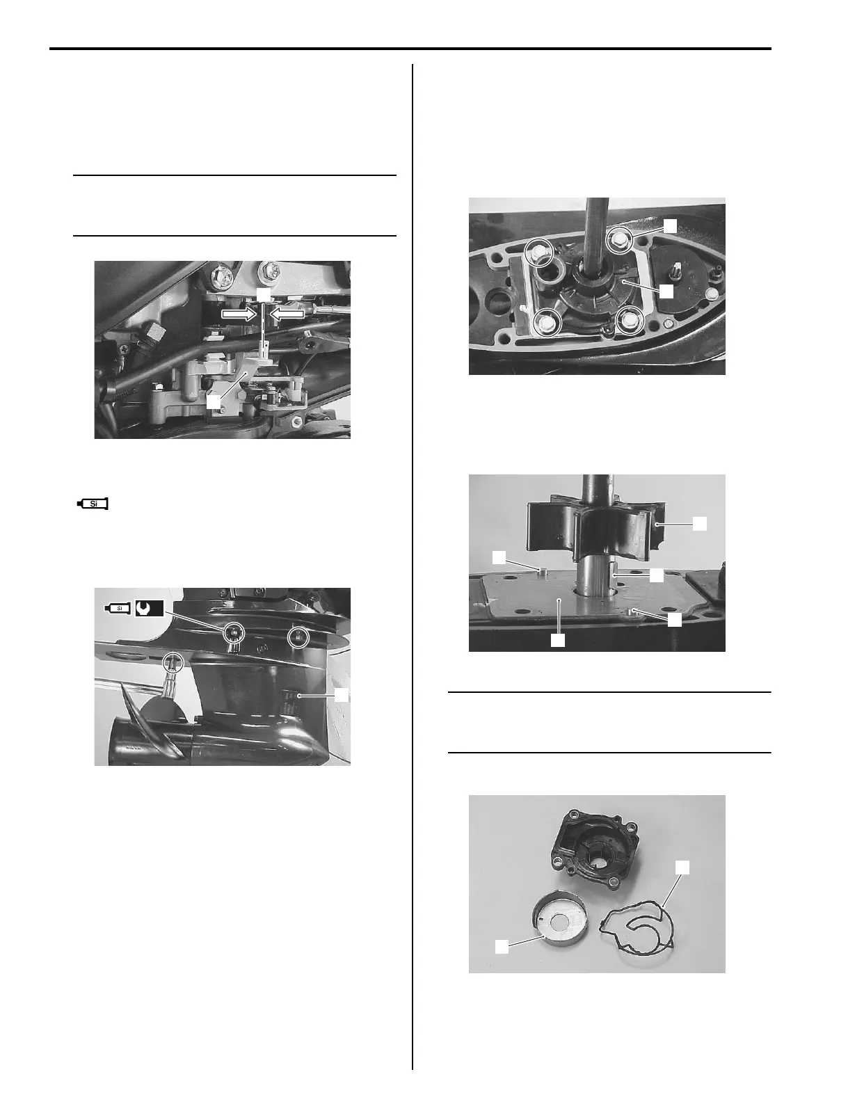
Water Pump Removal and Installation
Z9J0113106012
Removal
1) Remove the lower unit. Refer to “Lower Unit
Removal and Installation” (Page 3A-5).
2) Loosen four bolts (1), then remove water pump case
(2).
3) Remove impeller (3), impeller key (4), pump under
plate (5) and dowel pins (6).
Keep impeller key (4) for reuse and discard the plate
gasket.
NOTE
To facilitate the removal of inner sleeve from
pump case, warm up the entire case using a
heater like hair dryer.
4) Remove inner sleeve (7) and rubber seal ring (8).
3
N
I9J011310026-01
(a)
4
I9J011310027-01
1
2
I9J011310028-01
3
4
5
6
6
I9J011310029-01
7
8
I9J011310030-01