1A-28 Engine General Information and Diagnosis:
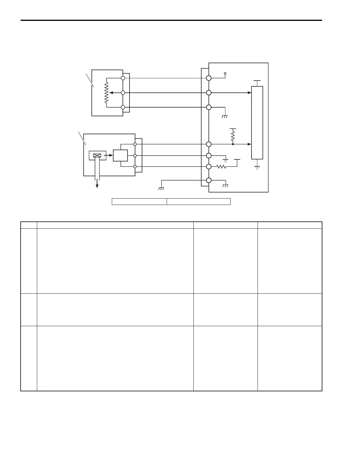
Self-Diagnostic Code “3 – 2” MAP Sensor 2
Z9J0111104009
Wiring Diagram
Troubleshooting
ECM
R
B/W
Br/Y
W
B/W
R
5V
5V
C
P
U
B
5V
+
1
2
I9J011110029-03
1. TPS 2. MAP sensor
Step Action Yes No
1 1) With the ignition switch “OFF”, disconnect the MAP
sensor connector.
2) With the ignition switch “ON”, check the voltage at the
“R” wire terminal of the MAP sensor connector.
Is the voltage approx 4 – 5 V?
Go to step 2. • “R” wire open, “R”
wire shorted to
ground circuit or poor
wire connection.
• If the wiring and
connection is OK,
substitute a known-
good ECM and
recheck.
2 1) Check the MAP sensor output voltage change.
Refer to “MAP Sensor Output Voltage Inspection” in
Section 1C (Page 1C-13).
Is it in good condition?
Go to step 3. Faulty MAP sensor.
3 1) With the ignition switch “OFF”, disconnect the TPS
connector.
2) With the ignition switch “ON”, check the voltage at the
“R” wire terminal of the TPS connector.
Is the voltage approx. 4 – 5 V?
Go to step 4. • “R” wire open, “R”
wire shorted to
ground circuit or poor
wire connection.
• If the wiring and
connection is OK,
substitute a known-
good ECM and
recheck.