2B-26 Power Trim and Tilt:
3) Connect the “R” (red) wire to positive (+) terminal,
and the “B” (black) wire to negative (–) terminal of a
12 V battery.
CAUTION
Each operation test must be performed
within 3 to 5 seconds to avoid overheat
damage to the relay coil.
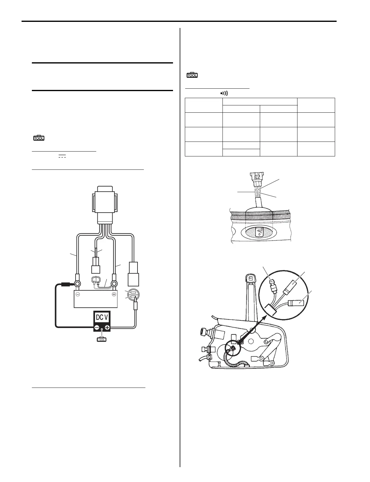
4) Temporarily connect a jumper wire (1) from the “P”
lead wire to the battery positive (+) terminal, then
check the voltage between the “G” wire and the “B”
wire.
Special tool
(A): 09930–99320 (Digital tester)
Tester knob indication
Voltage ( )
Voltage between “G” wire and “B” wire
12 V (Battery voltage)
5) Temporarily connect a jumper wire from the “Lbl”
lead wire to the battery positive (+) terminal, then
check the voltage between the “Bl” wire and the “B”
wire.
Voltage between “Bl” wire and “B” wire
12 V (Battery voltage)
6) If inspection in step 2 and/or step 4, 5 fails, replace
PTT motor relay.
7) Install the PTT motor relay to the electric parts
holder.
Refer to “Electric Parts Holder Removal and
Installation” in Section 1D (Page 1D-5).
PTT Switch Inspection
Z9J0112206014
Test continuity between the switch lead wires at each of
the three switch positions.
If out of specification, replace PTT switch.
Special tool
: 09930–99320 (Digital tester)
Tester knob indication
Continuity ( )
R
1
Bl
G
12 V
P
Lbl
B
BATT.
(A)
I9J011220047-01
Tester probe connection Tester
indicatesRed (+) Black (–)
DN side
depressed
Terminal (2) Terminal (1) Continuity
UP side
depressed
Terminal (3) Terminal (1) Continuity
Not
depressed
Terminal (2)
Terminal (1) Infinity
Terminal (3)
(P)
(Lbl)
2
3
(W/R)
1
I9J011220048-02
(Lg)
(Lbl)
(R)
3
2
1
I9J011220049-03