1A-26 Engine General Information and Diagnosis:
Self-Diagnostic Code “2 – 4” CMP Sensor
Z9J0111104007
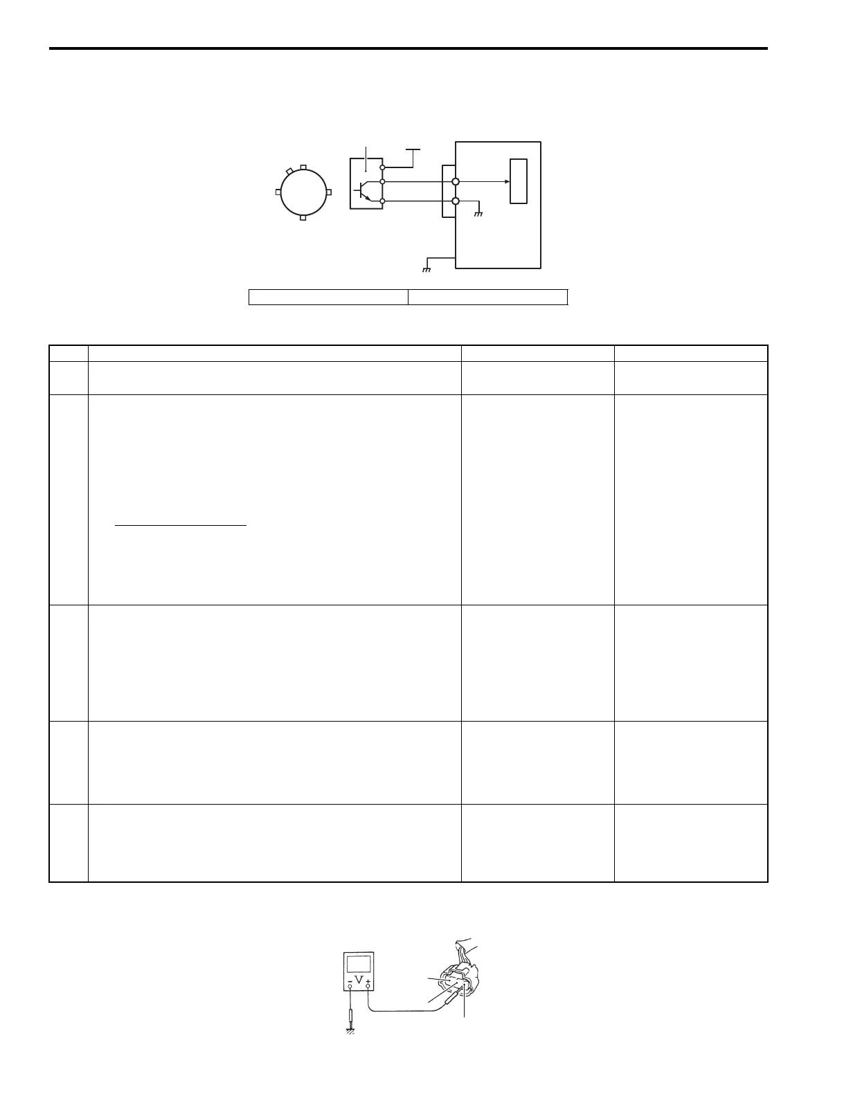
Wiring Diagram
Troubleshooting
For step 2
1. CMP sensor 2. + 12 V (From Ign. switch)
ECM
Y/Bl
B/W
B/Bl
C
P
U
1
2
I9J011110055-01
Step Action Yes No
1 Is the CMP sensor installed properly and the wire harness
connected securely?
Go to step 2. Correct.
2 1) Disconnect the connector from the CMP sensor.
2) Check for proper connection to the CMP sensor at “B/
Bl”, “Y/Bl” and “B/W” wire terminals.
3) If OK, turn the ignition switch “ON” and check the voltage
at the “B/Bl”, “Y/Bl” and “B/W” wire terminals of the CMP
sensor connector.
CMP sensor voltage
Terminal “B/Bl”: 10 – 14 V
Terminal “Y/Bl”: 4 – 5 V
Terminal “B/W”: 0 V
Is the voltage satisfactory?
Go to step 5. Go to step 3.
3 Was terminal “Y/Bl” voltage in step 2 within specification? Go to step 4. “Y/Bl” wire open or
shorted to ground /
power supply circuit. If
the wiring and
connection is OK,
substitute a known-
good ECM and recheck.
4 Was terminal “B/Bl” voltage in step 2 within specification? Go to step 5. “B/Bl” wire open circuit.
If the wiring and
connection is OK,
substitute a known-
good ECM and recheck.
5 Check the CMP sensor and sensor trigger vane.
Refer to “CMP Sensor Inspection” in Section 1C (Page 1C-
11).
Is check result satisfactory?
Substitute a known-
good ECM and recheck.
Replace CMP sensor.
B/Bl
Y/Bl
B/W
I9J011110056-01