1K-1 Charging System:
Power Head
Charging System
General Description
Charging System Description
Z9J0111B01001
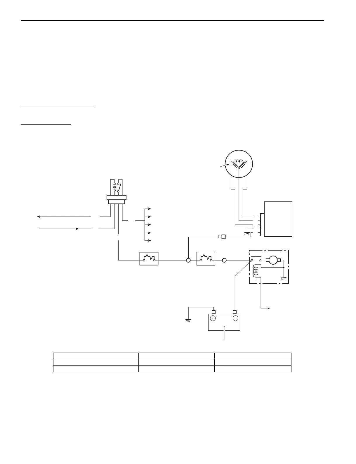
The battery charging system circuit is illustrated below.
It is composed of the Battery Charge Coil, Rectifier/regulator and Battery. The three phase AC current generated from
the battery charge coil is converted by the rectifier/regulator into regulated DC current which is used to charge the
battery.
Battery Charge coil Output
Standard: 12 V 27 A (324 W) at 3 000 r/min
Regulated Voltage
Standard: 14.5 – 15.2 Volts
M
+
–
WW
To ECM
To Fuel injector
To Ign. coil
To Fuel pump
Other
To ECM
From Ign. switch
To Starter relay
Gr
P/B
W
W
Y
Y
R
Y
B
8
7 6
5
1
2
3
4
I9J0111B0001-03
1. Alternator (Magneto) 4. Starter motor 7. ECM fuse 30 A
2. Battery charge coil 5. Battery 8. Main relay
3. Rectifier/Regulator 6. Main fuse 40 A