1G-23 Fuel System:
Special tool
(A): 09930–88730 (36-pin test cord set)
: Stevens peak reading voltmeter CD-77
Tester knob indication
NEG 50
1) Disconnect all ignition coil connectors from the ignition coils.
2) Connect the test cord between the ECM and wire harness as shown in figure, then turn ignition switch “ON”.
3) Connect the tester probe (“–”, Black) to the starter motor magnetic switch terminal “B” (connected to battery
positive (+) terminal) as shown in figure.
4) Connect the tester probe (“+”, Red) to each terminal.
5) Crank the engine and measure the voltage.
If out of specification, inspect the related parts as described in “Fuel System Diagnostic Information / Fuel Injection
System Troubleshooting”.
Refer to “Fuel System Diagnosis” (Page 1G-13) and “Fuel Injection System Troubleshooting” (Page 1G-14).
Fuel injector operating signal
Standard: Approx. 6 – 10 V or over
Fuel Injector Removal and Installation
Z9J0111706013
Removal
1) Relieve the fuel pressure in the fuel feed line
according to “Fuel Pressure Relief Procedure”.
Refer to “Fuel Pressure Relief Procedure” (Page 1G-
15).
2) Remove the ring gear cover.
Refer to “Ring Gear Cover Removal and Installation”
in Section 1D (Page 1D-2).
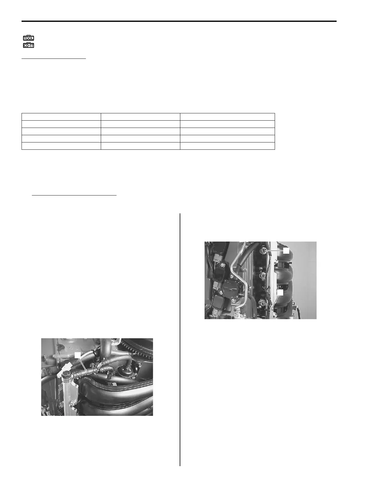
3) Loosen the clamp and place a large cloth over the
end of the fuel feed hose (1).
Slowly pull the fuel feed hose from the fuel delivery
pipe.
Drain any excess fuel in the hose into a small
container.
4) Disconnect the four fuel injector connectors (2).
Cut the cable tie (3) binding the fuel injector lead
wire to the fuel delivery pipe.
Injector Terminal Wire color (Engine harness)
No.1 45 O/B
No.2 71 B/Br
No.3 47 R/W
No.4 59 Lg
1
I9J011170057-01
2
3
I9J011170058-02