1A-42 Engine General Information and Diagnosis:
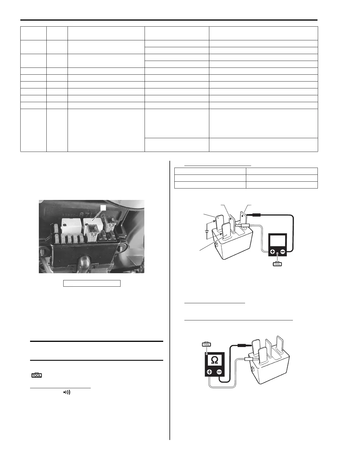
ECM Main Relay Inspection
Z9J0111106003
Inspect the ECM main relay using the following
procedures:
1) Disconnect the ECM main relay from the fuse box.
2) Check continuity between terminal (2) and (3) each
time 12 V power supply is applied to terminal (4) and
(5).
Connect the positive (+) lead to terminal (5), and
negative (–) lead to terminal (4).
CAUTION
Be careful not to touch 12 V power supply
wires to each other or with other terminals.
Special tool
(A): 09930–99320 (Digital tester)
Tester knob indication
Continuity ( )
ECM main relay function
3) Measure the resistance between relay terminals (4)
and (5).
If out of specification, replace ECM main relay.
Tester knob indication
Resistance (Ω)
ECM Main relay solenoid coil resistance
Standard: 145 – 190 Ω
64 O/W Buzzer cancel
Approx. 12 V Ignition switch ON. Key pushed in.
Approx. 0 V Ignition switch ON. Key not pushed in.
65 Br Starter switch
Approx. 2.5 V Ignition switch ON.
Approx. 12 V Ignition switch START position.
66 Bl/B OIL lamp — —
67 — — — —
68 — — — —
69 G/W CHECK ENGINE lamp — —
70 R/Y IAC Valve #2 Approx. 12 V or 0 V Ignition switch ON.
71 B/Br No.2 Fuel injector (–) Approx. 12 V Ignition switch ON.
72 B/R High pressure fuel pump (–)
Approx. 0 V
• Stop switch plate IN, Shift into
NEUTRAL.
For 3 sec after ignition switch ON.
• While engine running.
Approx. 12 V
Engine stopped. Ignition switch ON.
Stop switch plate IN, Shift into NEUTRAL.
Terminal
Wire
color
Circuit Standard Voltage Condition / Remarks
1. ECM main relay
1
I9J011110054-02
Continuity
12 V power applied Yes
12 V power not applied No
CONT
12 V
2 3
4
5
(A)
I9J011110038-02
(A)
I9J011110039-01