Fuel System: 1G-16
Fuel Leakage Check Procedure
Z9J0111706004
After performing any fuel system service, always be sure
there is no fuel leakage by checking as follows.
1) Squeeze fuel primer bulb until you feel resistance.
2) Shift into “Neutral” position.
3) Ensure emergency stop switch lock plate is in place.
4) Turn ignition switch “ON” for 3 seconds (to operate
fuel pump), then turn it “OFF”.
Repeat this (“ON” and “OFF”) procedure 3 or 4 times
to pressurize the fuel system.
5) Once pressurized, check all connections and
components for any signs of leakage.
Inspection of Fuel Hose Connections
Z9J0111706005
Note that the fuel hose connection varies with each type
of pipe. Be sure to connect and clamp each hose
correctly by referring to the figure.
• For type “A” (short barbed end) pipe, the hose must
completely cover pipe.
Type “A”
• For type “B” (bent end) pipe, hose must cover the
straight part of pipe by 20 – 30 mm (0.8 – 1.2 in.).
Type “B”
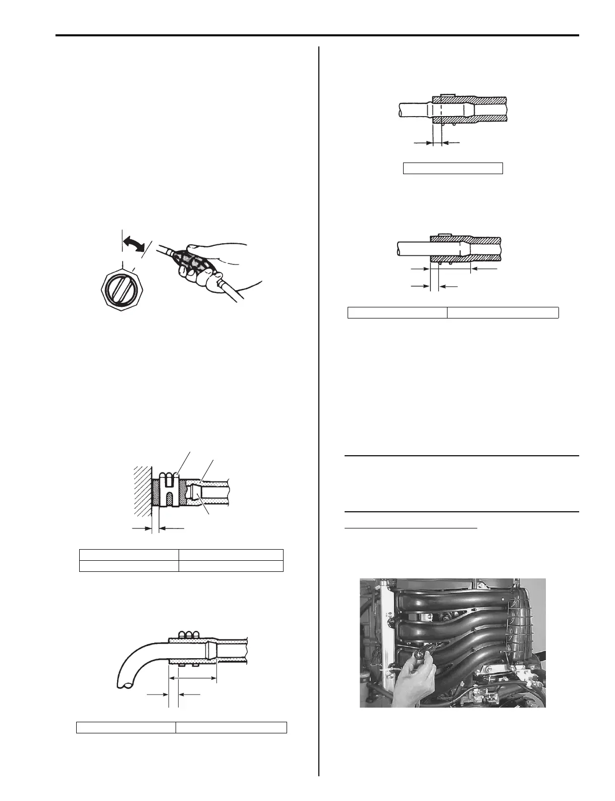
• For type “C” pipe, hose must fit up against the flanged
part of pipe.
Type “C”
• For type “D” pipe, the hose must cover the pipe by 20
– 30 mm (0.8 – 1.2 in.).
Type “D”
High Pressure Fuel Pump Operating Sound
Inspection
Z9J0111706006
1) Install the emergency stop switch lock plate into
position.
2) Shift into “Neutral”.
3) Turn ignition switch “ON” and check for fuel pump
operating sound.
NOTE
Fuel pump operating sound is low because
the pump is inside the fuel vapor separator. If
you cannot hear the pump sound clearly, use
a sound scope or long blade screw driver.
Fuel pump operating sound
Sounds for approx. 3 seconds only
(each time the ignition is turned to the “ON”
position)
1. Clamp (Clip) 3. Joint pipe
2. Hose “a”: 3 – 7 mm (0.1 – 0.3 in)
“a”: 3 – 7 mm (0.1 – 0.3 in) “b”: 20 – 30 mm (0.8 – 1.2 in)
OFF
ON
I9J011170020-01
1
2
3
“a”
I9J011170012-01
“a”
“b”
I9J011170013-01
“a”: 3 – 7 mm (0.1 – 0.3 in)
“a”: 3 – 7 mm (0.1 – 0.3 in) “b”: 20 – 30 mm (0.8 – 1.2 in)
“a”
I9J011170014-01
“a”
“b”
I9J011170015-01
I9J011170031-01