Engine General Information and Diagnosis: 1A-27
Self-Diagnostic Code “2 – 2” Air Intake System
Z9J0111104008
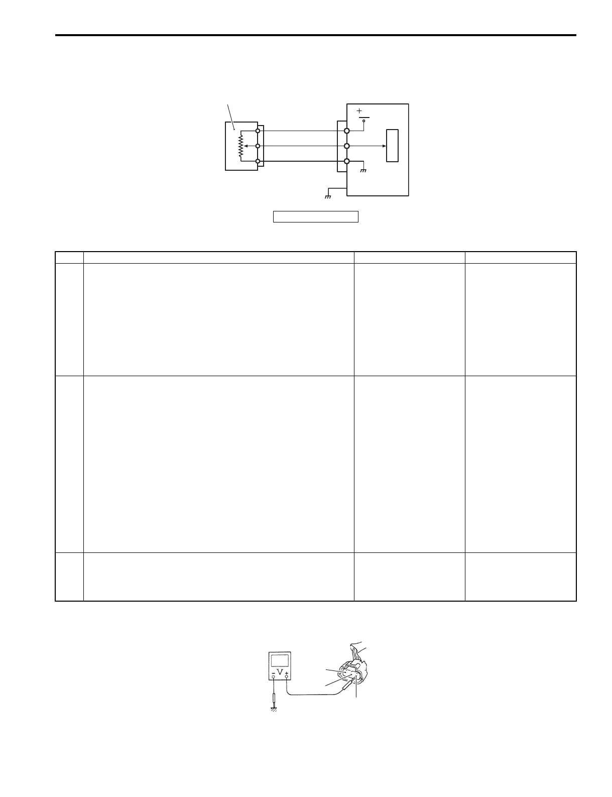
Wiring Diagram
Troubleshooting
For step 1
1. TPS
ECM
R
B/W
Br/Y
C
P
U
5V
1
I9J011110057-01
Step Action Yes No
1 1) With the ignition switch “OFF”, disconnect the TPS
connector.
2) With the ignition switch “ON”, check the voltage at the
“R” wire terminal of TPS connector.
Is the voltage approx. 4 – 5 V?
Go to step 2. • “R” wire open, “R”
wire shorted to
ground circuit or poor
wire connection.
• If the wiring and
connection is OK,
substitute a known-
good ECM and
recheck.
2 1) Check the TPS output voltage change.
Refer to “TPS Inspection” in Section 1C (Page 1C-15).
Is it in good condition?
Go to step 3. • Faulty TPS.
• “R” wire shorted to
“Br/Y” wire, “B/W”
wire open, poor “B/
W” wire connection,
poor “Br/Y” wire
connection, “Br/Y”
wire open or poor
TPS connection.
• If the wiring and
connection is OK,
intermittent trouble or
a faulty ECM may be
the cause.
3 1) Check the MAP sensor, IAC system and intake manifold
(system) for air leakage.
Is the result OK?
Intermittent trouble or
faulty ECM. Substitute a
known-good ECM and
recheck.
Faulty air intake system.
R
Br/Y
B/W
I9J011110058-01